Wells WV-4HSRW operation manual Filters Installation, Filter Installation

Page 13

INSTALLATION (continued)

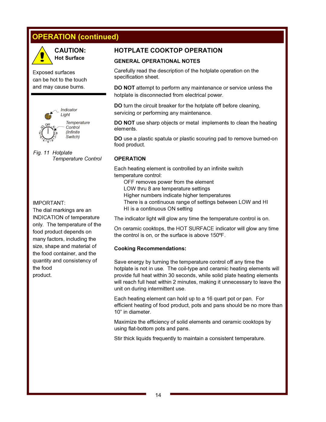
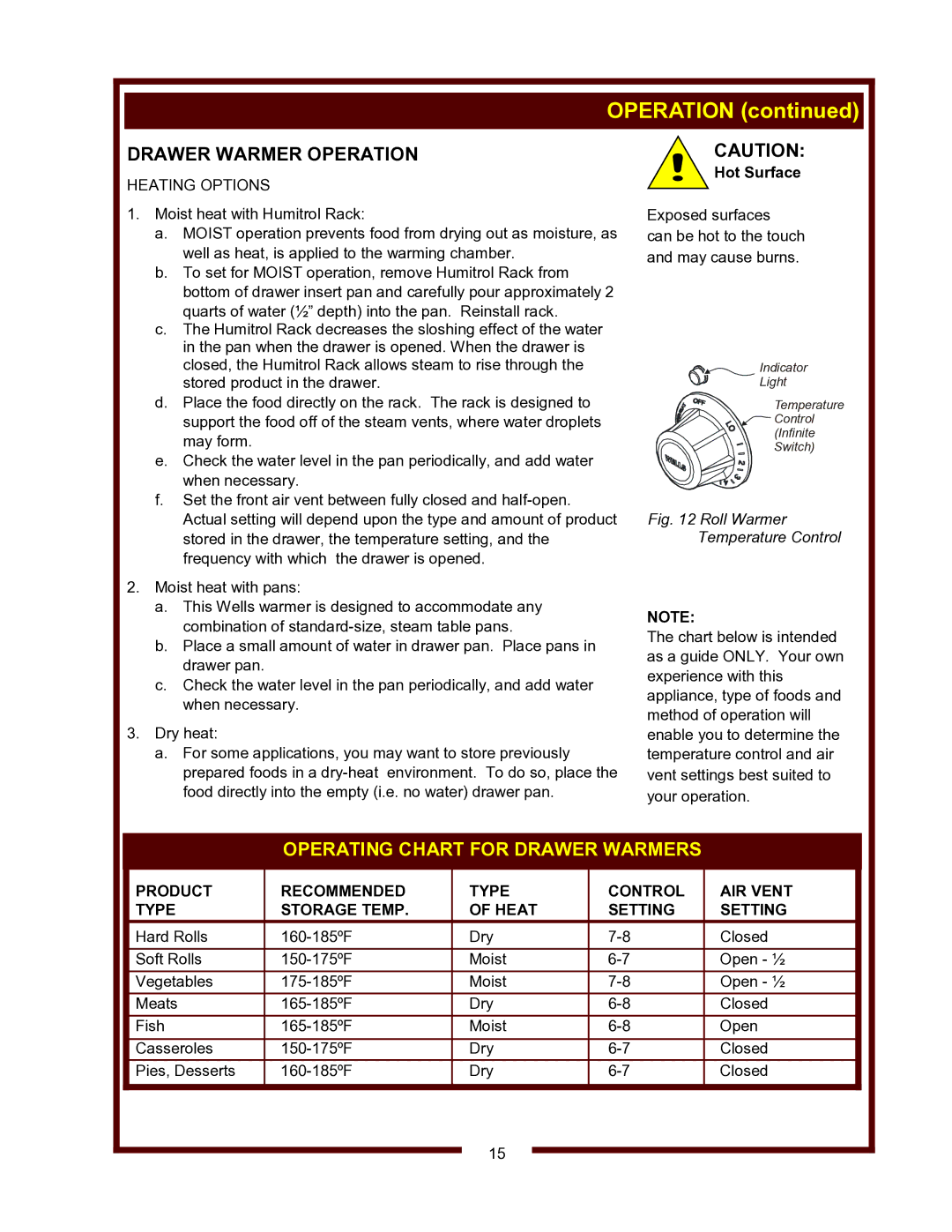
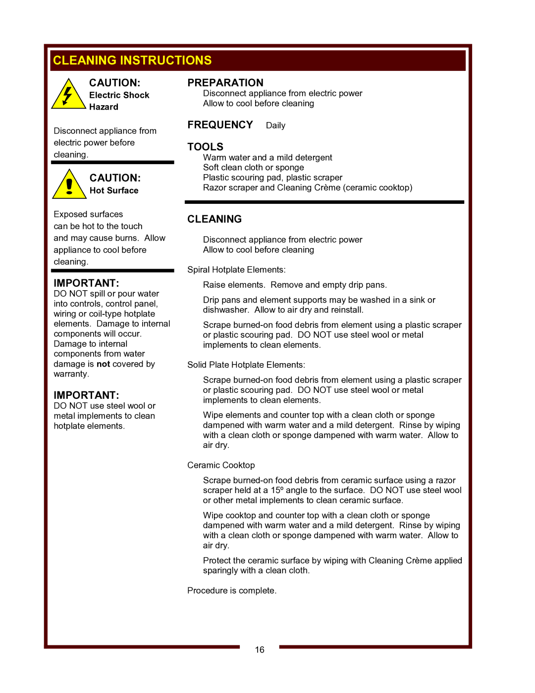
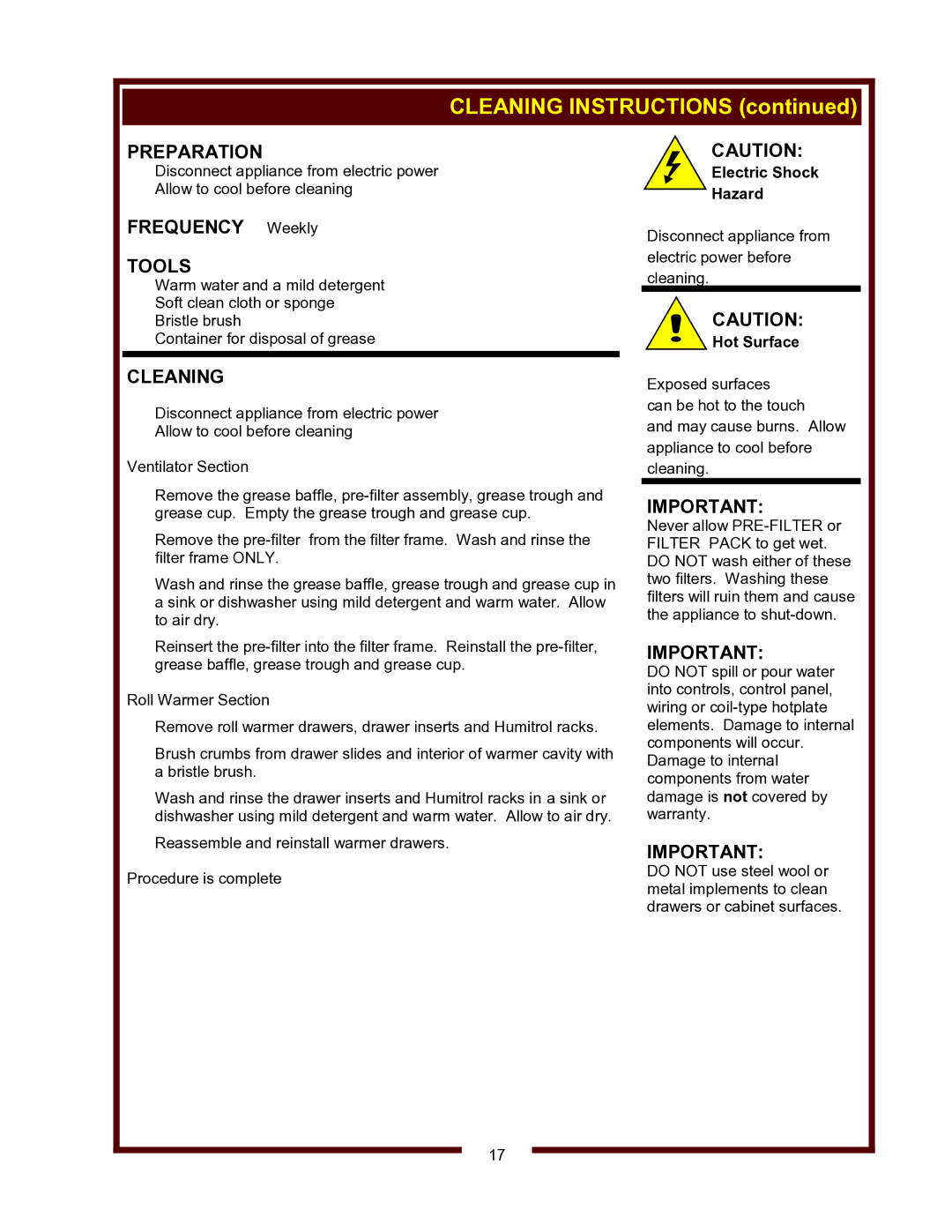
FILTERS INSTALLATION

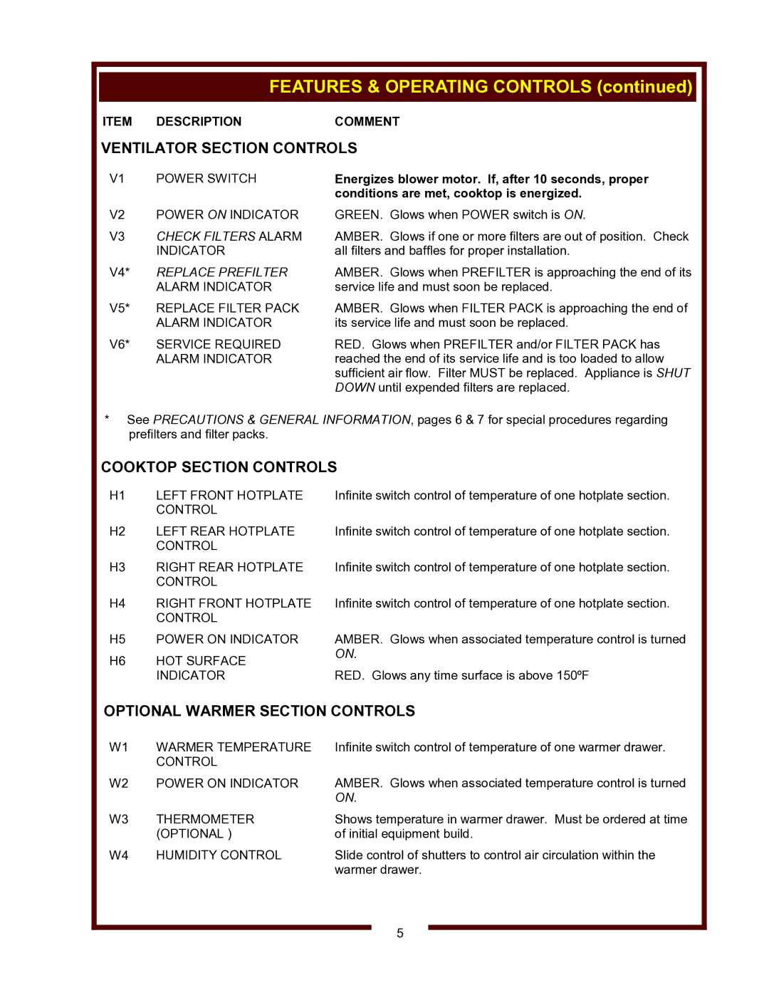
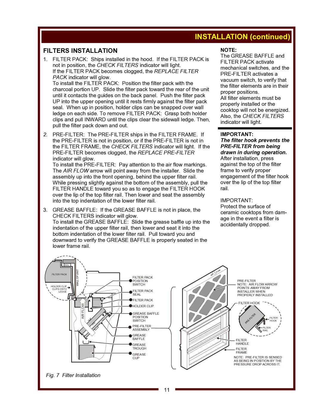
1.FILTER PACK: Ships installed in the hood. If the FILTER PACK is not in position, the CHECK FILTERS indicator will light.

If the FILTER PACK becomes clogged, the REPLACE FILTER PACK indicator will glow.

To install the FILTER PACK: Position the filter pack with the charcoal portion UP. Slide the filter pack toward the rear of the unit until it contacts the guides on the back panel. Push the filter pack UP into the upper opening until it rests firmly against the filter pack seal. When up in position, holder clips can be snapped over wall ledge on each side. To remove FILTER PACK: Grasp both holder clips and pull INWARD until the clips clear the sidewall ledge. Then, pull the filter pack down and out.

2.PRE-FILTER: The PRE-FILTER ships in the FILTER FRAME. If the PRE-FILTER is not in position, or if the PRE-FILTER is not in the FILTER FRAME, the CHECK FILTERS indicator will light. If the PRE-FILTER becomes clogged, the REPLACE PRE-FILTERindicator will glow.

To install the PRE-FILTER: Pay attention to the air flow markings. The AIR FLOW arrow will point away from the installer. Slide the assembly up into the front opening, behind the upper filter rail.

While pressing slightly against the bottom of the assembly, pull the FILTER HANDLE toward you so as to engage the FILTER HOOK over the lip of the top filter rail. Then lower and seat the assembly into the top indentation of the lower filter rail.

3.GREASE BAFFLE: If the GREASE BAFFLE is not in place, the CHECK FILTERS indicator will glow.

To install the GREASE BAFFLE: Slide the grease baffle up into the indentation of the upper filter rail, then lower and seat it into the bottom indentation of the lower filter rail. Pull toward you and downward to verify the GREASE BAFFLE is properly seated in the lower frame rail.

NOTE:

The GREASE BAFFLE and FILTER PACK activate mechanical switches, and the PRE-FILTER activates a vacuum switch, to verify that the filter elements are in their proper positions.

All filter elements must be properly installed or the cooktop will not be energized. Also, the CHECK FILTERS indicator will light.

IMPORTANT:

The filter hook prevents the PRE-FILTER from being drawn in during operation. After installation, press against the top of the filter frame to verify proper engagement of the filter hook over the lip of the top filter rail.
IMPORTANT: Protect the surface of ceramic cooktops from dam- age in the event a filter is accidentally dropped.

SEAL

FILTER PACK

HOLDER CLIP CLIPS ONTO LEDGE

OFUNIT

FILTER PACK

WALL

POSITION

SWITCH


FILTER PACK


SEAL

FLOW

FILTER PACK

HOLDER CLIP


AIR

GREASE BAFFLE

POSITION


SWITCH


PRE-FILTER


ASSEMBLY


GREASE


BAFFLE


GREASE


TROUGH


GREASE


CUP

PRE-FILTER

NOTE: AIR FLOW ARROW

POINTS AWAY FROM INSTALLER WHEN PROPERLY INSTALLED

FILTER HOOK


R


E


T


FILTER

IL


-F


HOOK

E


R


P


FILTER

RAIL

FILTER HANDLE

FILTER FRAME

NOTE: PRE-FILTER IS SENSED

AS BEING IN POSITION BY THE

PRESSURE DROP ACROSS IT.

Fig. 7 Filter Installation

11

Image 13
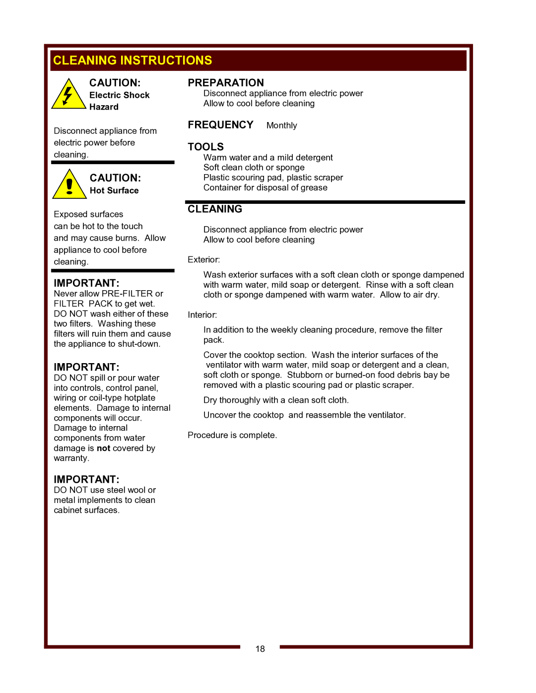
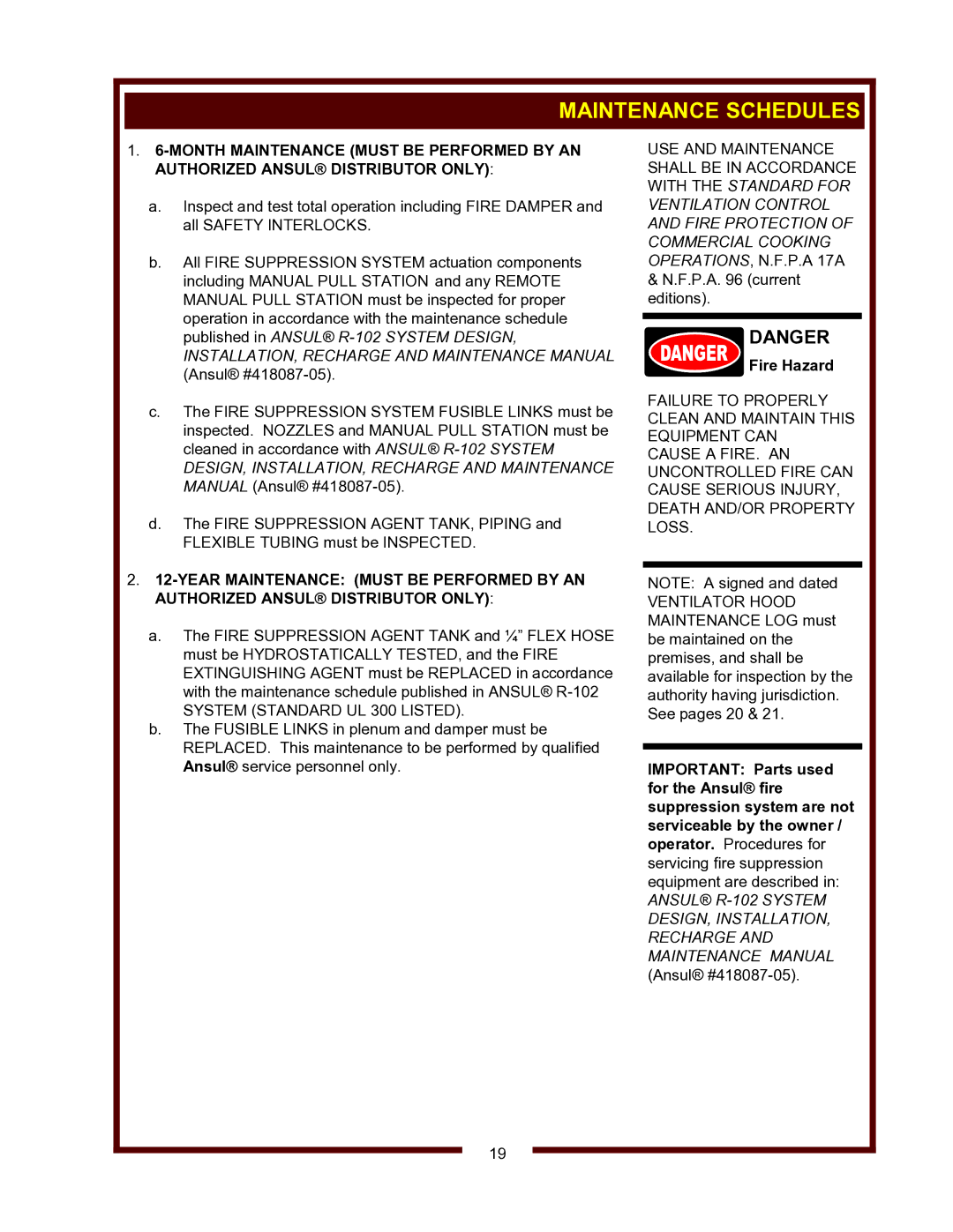
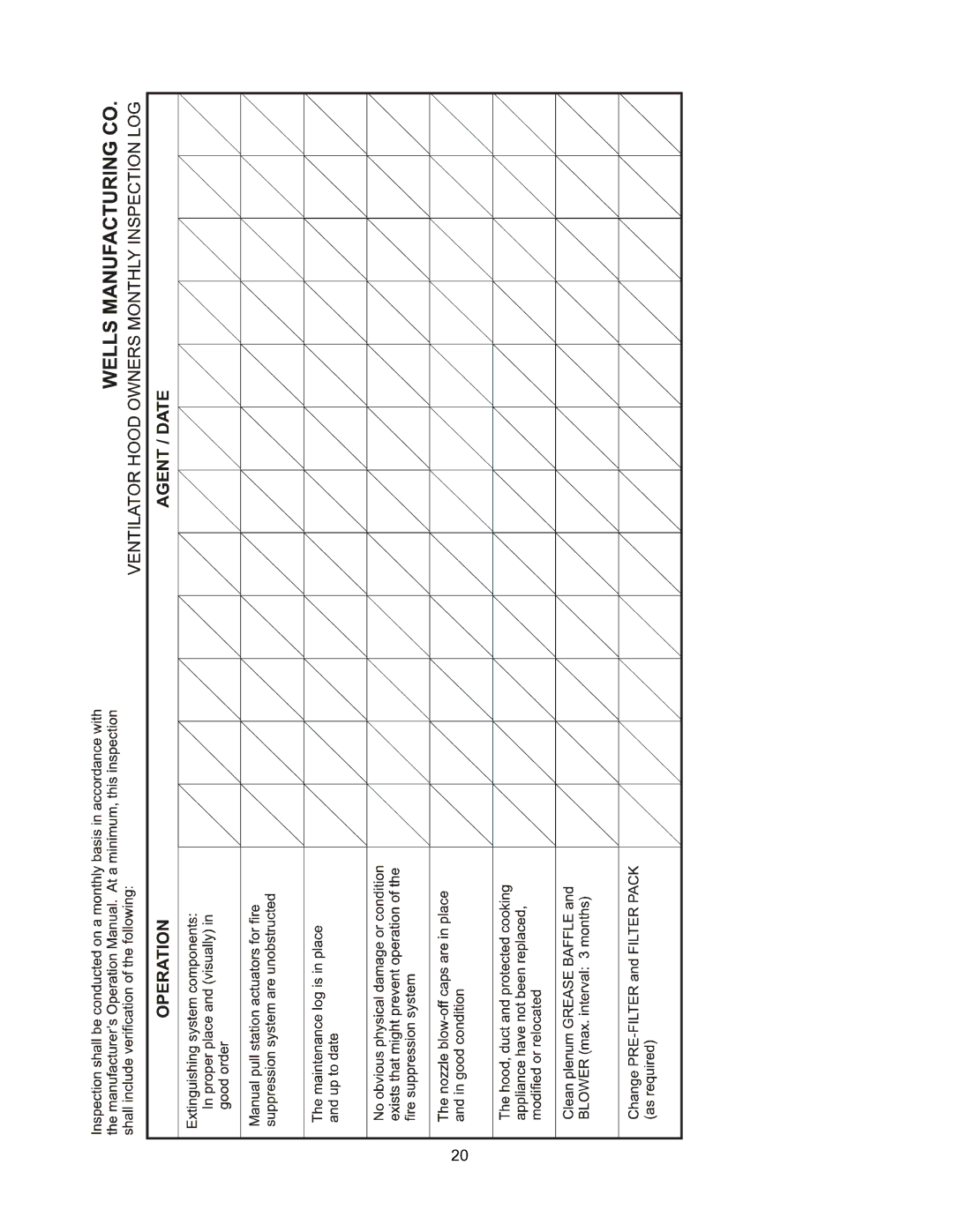
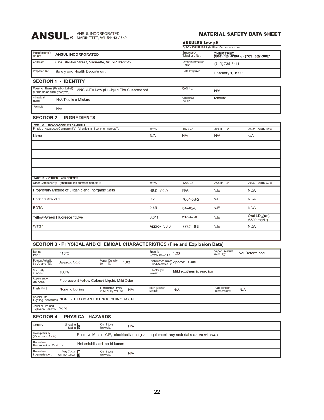
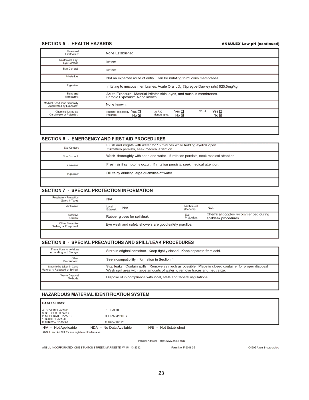
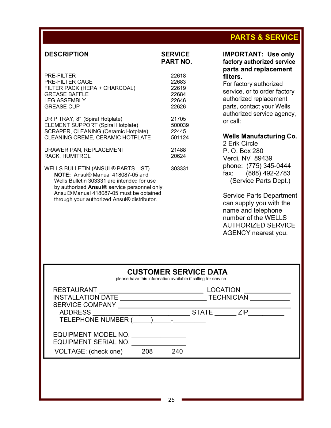
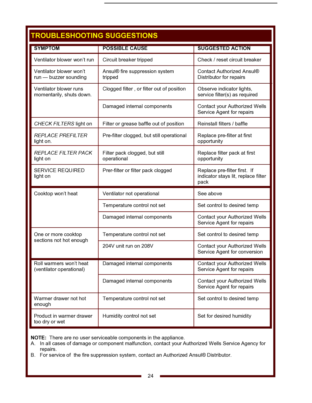
Contents Important do not Discard this Manual 504Limited Warranty Statement Specifications Table of ContentsIntroduction Ventilator Section Operating Features & Controls Features & Operating ControlsVentilator Section Features & Operating ControlsDescription Comment Do not BlockFeatures & Operating Controls Cooktop Section Controls Ventilator Section ControlsOptional Warmer Section Controls Electric Shock hazard Precautions and General InformationAgency Listing Information Precautions and General InformationOperational Notes STDSetup InstallationUnpacking & Inspection Service Technician Installation Notes InstallationElectrical Installation This is Responsibility InstallerFire Hazard Fire Suppression System InstallationAuthority Having Jurisdiction Filter Installation Filters InstallationHotplate Drip PAN Installation Spiral Heating Elements only Grease Trough and Grease CUP InstallationRoll Warmer Installation Do not Operate Unless Grease CUP is InstalledVentilator Operation OperationPRE-FILTER Element Hotplate Cooktop Operation OperationGeneral Operational Notes OperationHeating Options Drawer Warmer OperationCleaning Cleaning InstructionsPreparation ToolsCleaning Instructions Frequency Monthly Fire Hazard Maintenance SchedulesPage Page Ansul Health Hazards Symptom Possible Cause Suggested Action Troubleshooting SuggestionsDescription Service Parts & Service

WV-4HSRW specifications

The Wells WV-4HSRW is a robust and versatile water well drilling rig designed for both the professional driller and the demanding environmental conditions often encountered in well drilling projects. This machine is particularly celebrated for its efficiency, ease of use, and the advanced technologies integrated into its design.

One of the standout features of the WV-4HSRW is its powerful hydraulic system. The rig utilizes a high-pressure hydraulic pump that delivers optimal performance, allowing for effective drilling in various soil conditions. The rig's hydraulic capabilities enable efficient rotary drilling and can accommodate a wide variety of drill bits, making it adaptable to different geological formations.

The WV-4HSRW is equipped with a 4-wheel drive system, which is crucial for maneuverability in rugged and uneven terrains. This feature ensures that the rig remains stable and can move seamlessly from one site to another, even in challenging conditions. Additionally, the rig's compact design enhances its ability to navigate tight spaces, which is often a necessity for residential and urban drilling projects.

Safety and operator comfort are paramount in the design of the Wells WV-4HSRW. The rig features an ergonomic cab that provides excellent visibility and protection for the operator. Moreover, the controls are intuitively laid out, which simplifies operation for both experienced drillers and those new to the field. The inclusion of safety features, such as emergency stop systems and reinforced structures, further enhances the safety profile of the rig.

In terms of power, the WV-4HSRW is often powered by efficient diesel engines that provide the necessary energy while remaining fuel-efficient. This not only reduces operational costs but also minimizes the environmental footprint, aligning with modern sustainability goals. The machine’s design allows for easy maintenance access, ensuring that routine checks and repairs can be carried out with minimal downtime.

Overall, the Wells WV-4HSRW represents a significant advancement in drilling technology, combining robust construction with innovative hydraulic systems, user-friendly controls, and enhanced safety features. Whether for water well drilling, geothermal projects, or environmental investigations, this rig is engineered to deliver reliability and effectiveness in every project it undertakes. Its blend of performance and versatility makes it an invaluable asset to any drilling operation.