CTG212FD specifications
The Verona CTG212FD is a modern gas range that stands out for its combination of performance, style, and innovative features, making it an excellent choice for both avid home cooks and professional chefs alike. This range is designed to bring the warmth and creativity of cooking back into the kitchen with a host of functionalities that elevate culinary experiences.One of the main features of the Verona CTG212FD is its dual-fuel capability. This means it combines the precision of a gas cooktop with the even heating of an electric oven. This hybrid system allows cooks to achieve better control over their stovetop cooking while benefiting from the consistency of baking with an electric oven. This dual-fuel design is perfect for a variety of cooking methods, from searing meats to baking delicate pastries.
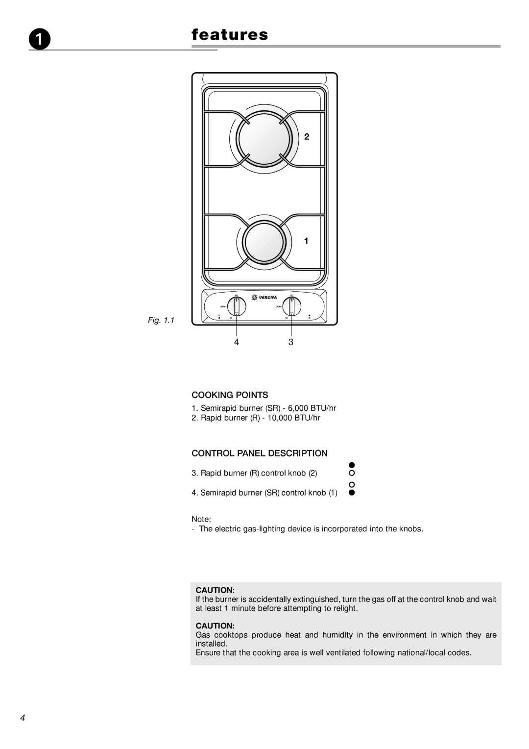
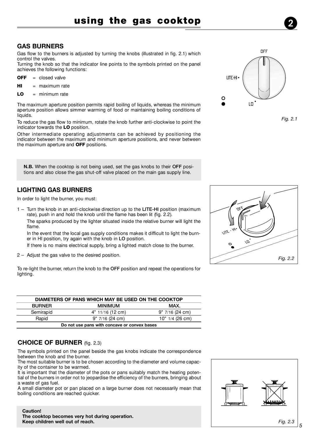
Another standout characteristic of the Verona CTG212FD is its powerful gas burners. The range comes equipped with multiple burners that offer different BTU outputs, allowing for a range of cooking needs. High-BTU burners are ideal for rapid boiling or frying, while lower-BTU burners provide gentle heat for simmering sauces or melting chocolate. This versatility ensures that home chefs can tackle any recipe with ease.
The design of the Verona CTG212FD is equally impressive. With a sleek stainless steel finish and a professional-grade look, it adds an element of elegance to any kitchen. The ergonomic control knobs and the large oven window provide both practical functionality and a chic aesthetic. Additionally, the oven features a spacious interior that accommodates various baking trays and dish sizes, making it suitable for batch cooking or preparing large family meals.
The Verona CTG212FD also boasts advanced technologies such as a convection oven that circulates hot air for even cooking results. This feature is crucial for baking, as it ensures that heat is distributed uniformly, allowing baked goods to rise perfectly and cook evenly. Moreover, the range offers self-cleaning capabilities, making maintenance simple and efficient for busy home chefs.
Overall, the Verona CTG212FD combines high performance, modern technology, and stylish design, making it a standout choice for anyone looking to enhance their cooking experience. Its dual-fuel system, powerful burners, elegant appearance, and user-friendly features create an ideal environment for culinary creativity.
