ELECTRICAL SCHEMATICS
00014
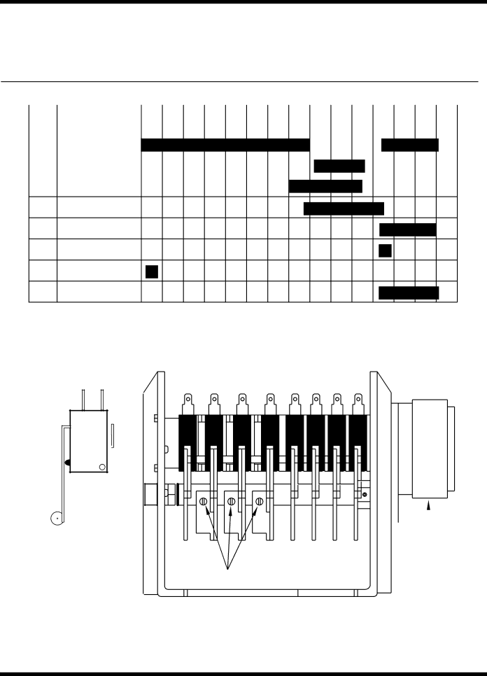
TIMING CHART 501HT
0 | 10 | 20 | 30 | 40 | 50 | 60 | 70 | 80 | 90 | 100 | 110 | 120 | 130 | 140 | 150 |
CAM | TIME IN SECS |
|
|
1 | HOMING |
|
|
|
| ||
CAM |
|
| |
|
| ||
2 | WASH PUMP |
|
|
FORWARD=WASH |
|
| |
|
|
| |
2 | WASH PUMP |
|
|
REVERSE=DRAIN |
|
| |
|
|
| |
| WASH PUMP |
|
|
3REVERSING CAM DRAIN VALVE
4DRAIN PUMP
5FILL VALVE RINSE
6OPTIONAL
PUMP
DETERGENT
7PUMP
8DRAIN
![]() N N
N N
C O
COM. ![]()
TIMER
SWITCH
DETAIL
SYNCHRON
8 | 7 | 6 | 5 | 4 | 3 | 2 | 1 |
|
|
|
|
|
| ||||||||
|
|
|
|
|
|
|
|
|
|
|
| LOCKING SCREW |
|
|
|
|
|
| TIMER MOTOR | ||
|
|
|
|
|
|
|
|
| ||
|
|
|
|
|
|
|
|
|
|
|
|
|
|
|
|
|
|
|
|
|
|
TIMER ASSEMBLY 501HT
Figure 22 - Timer Chart and Diagram, 501-HT
(Prior to S/N W7603)
51