3C13701 3C13751 3C13755 3C13759 3C13840 3C13880
3Com Router 5000 Family Router 6000 Family Module Guide
3Com Corporation Campus Drive Marlborough, MA 01752-3064
Table of Contents
Router 2-Port FXS/FXO/E&M MIM Modules
3Com Router 5000 and Router 6000 Module Guide
3Com Router 5000 and Router 6000 Module Guide
Table of Contents Interface LEDs Interface Cable
3Com Router 5000 and Router 6000 Module Guide
Vii
3Com Router 5000 and Router 6000 Module Guide
Types of MIMs
Types of SICs
Types of FICs
SIC/MIM Purchasing Guideline
Installation/Removal of SIC and MIM
III. Installing SIC
Installing/Removing SIC
Tools required
II. Removing blank filler panel from SIC slot
Installing/Removing MIM
II. Installing MIM
IV. Removing SIC
III. Removing MIM
Installing/Removing an FIC
Troubleshooting
Router 1-Port 10/100 SIC
Interface Attributes
Attribute Router 1-Port 10/100 SIC
Interface Cable
Connecting the Interface Cable
Introduction
Router 1-Port Serial SIC
Synchronous and asynchronous
24 RS232 Maximum Baud rate bps Transmission Distance m
II. DTE and DCE
Appearance
Equipment type Interface type Typical equipment
DTE
DTE, DCE
Attribute Description Synchronous Asynchronous
Interface LEDs
5V.24 RS232 DTE cable 24 RS232 DCE cable
7V.35 DTE cable 35 DCE cable
Connecting Interface Cable
9Router 2-Port ISDN-S/T SIC
Router 2-Port ISDN-S/T SIC and Router 2-Port ISDN-U SIC
Isdn
Attribute Description
LED
Connecting Interface Cable
13Router 1-Port Fractional E1 SIC
Router 1-Port Fractional E1 SIC
DIP Switch
DIP switch Description Ohm Ohm impedance Impedance
8BIT
Module Guide
Ot-s h rink able tu be Pos.15
Connecting Interface Cable
BNC
20Router 1-Port Fractional T1 SIC
Router 1-Port Fractional T1 SIC
12Interface attributes of Router 1-Port Fractional T1 SIC
22 T1 cable
Router 1-Port Analog Modem SIC
Attribute Description Connector type RJ11
Blinking means the connection is being set up
Connecting Interface Cable
25Router 1-Port FXS/FXO SIC Router 2-Port FXS/FXO SIC
27Router 1-Port FXS SIC panel
29Router 2-Port FXS SIC panel
Router 1-Port SAE SIC
31Router 1-Port SAE SIC panel
32V24 DTE cable 24 DCE cable
33V.24 DCE cable 35 DTE cable
37X.21 DCE cable RS449 DTE cable
RS530 DCE cable
Router 2-Port FXS/FXO/E&M MIM module
Multifunctional Interface Modules Router
1Router 2-Port FXS/FXO/E&M MIM MOdule
II. Router 4-Port FXS/FXO/E&M MIM module
3Router 2-Port FXS panel
7Router 4-Port FXO panel
Interface cable of FXS/FXO modules
PBX
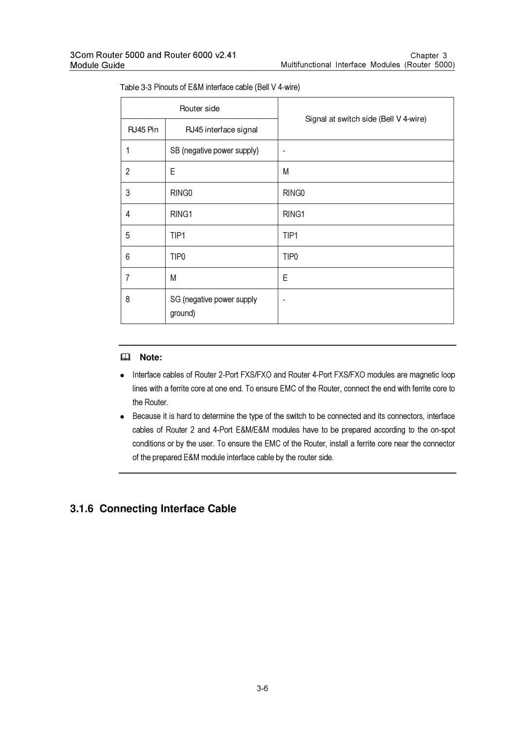
II. Interface cable of E&M modules
RING0 RING1 TIP1 TIP0
Router E1 Voice Module
Isdn PRI
11Router E1Voice Module
Active
Connecting Interface Cable
Router T1 Voice Module
CT1
16Router T1Voice Module
Received or/and transmitted
T1VI cable
20 Ndec
Ndec Module
RUN
Speed
Deny
Troubleshooting
Attribute Description Router 2-Port 10/100 MIM
Router 2-Port 10/100 MIM
II. Making Ethernet cables
Ethernet cable
Router 4-Port Serial MIM Module
24 RS232 Baud rate bps Maximum transmission Distance m Bps
II. Introduction to DTE and DCE
DTE DCE
Router 4-Port Serial MIM interface cable
DB100 male
Connecting interface cable of Router 4-Port Serial MIM
Router 2 and 4-Port Enhanced Serial MIM
DTE and DCE
Interface Attributes
Following figures show the 2 and 4-port panels
26 2-port panel
28V24 DTE cable 24 DCE cable
32X.21 DTE cable 21 DCE cable
36RS530 DTE cable RS530 DCE cable
Router 2 and 4-Port CE1/PRI MIM Modules
4-Port CE1/PRI
Attribute Description Port module
38 2-port panel
412-port 120-ohm balanced twisted pair cable
Interface cable of 2-port modules
II. Conversion cable for 4-port module
42120-ohm 4-port module conversion cable
Internal DIP Switches
8BIT
3BIT OFF 4BIT 5BIT
45Extending an 75-ohm unbalanced coaxial cable
Connecting interface cable of 1E1/2E1 and modules
II. Connecting interface cable of 4-port
Router 4-Port ISDN-S/T MIM Module
DIP switch Description Default Setting
49ISDN S/T cable
Router 2-Port CT1/PRI MIMmodule
Router 2-Port CT1/PRI MIM
LP/AL
LINK/ACT
51 T1 cable
Router 1-Port Adsl Over Pots MIM
Panel and Interface LED
Pots MIM
Attribute Router 1-Port Adsl Over
29LEDs on the Router 1-Port Adsl Over Pots MIM panel
Router 2-Port Adsl Over Pots MIM
Attribute
Router 2-Port Adsl Over
Panel and Interface LED
Router NDEC2 Encryption Accelerator MIM
56Connecting the Router 2-Port Adsl Over Pots MIM
57Router NDEC2 Encryption Accelerator MIM
Feature Description
Status
Indication
Router 4-Port E1 IMA MIM
Appearance of the Interface Card
E1 IMA MIM
AAL5
Panels and Interface LEDs
Meaning
Connection of the Interface Cable
Router 4-Port T1 IMA MIM
Introduction to the Interface card
Router 4-Port T1 IMA MIM
OFF the link is disconnected
SMB
Router 1-Port CE3 MIM Module
65 E3/T3 cable
Router 1-Port CT3 MIM Module
Router 1-Port CT3 MIM panel is shown in the following figure
Router 1-Port 10/100/1000 MIM
Attribute Router 1-Port 10/100/1000 MIM
MDI/MDIX
68Ethernet cable
Router 2-Port 10/100 FIC
Panel and Interface LEDs
Attribute Description Router 2-Port 10/100
2Ethernet cable
Router 1-Port 100FX MM FIC/100FX SM FIC
Attribute Description 100FX SM 100FX MM
Attribute Description 100FX SM 100FX MM EthernetSNAP
Interface Optical Fiber
Connecting the Interface Optical Fiber
Attribute Port 10/100/1000 FIC
Router 1-Port 10/100/1000 FIC
7Ethernet cable
Attribute Port Gigabit Ethernet FIC
Router 1-Port Gigabit Ethernet Fiber FIC
OFF means no link is present on means a link is present
1-Port GEF FIC
Connecting the Interface Optic Fiber
SFP
Attribute Port GEF FIC
Interface Cable
Router 4-Port/8-Port Enhanced Serial FIC
3Com Router 5000 and Router 6000 Module Guide
Interface Attributes
Panel and Interface LEDs
14V24 DTE cable 24 DCE cable
17V.35 DCE cable 21 DTE cable
21RS449 DCE cable RS530 DTE cable
Router 4-Port CE1/PRI FIC
Connector DB-25
Router 4-Port CE1/PRI FIC
Attribute Router 4-Port CE1/PRI
OFF means no link is present on means a link is present
Description Attribute Router 4-Port CE1/PRI
Interface cable of the Router 4-Port CE1/PRI FIC
27120-ohm 4E1 adapter cable
II. Interface cable of the Router 4-Port CE1/PRI FIC
Card Router 4-Port CE1/PRI FIC
Internal DIP Switch
29Extending an E1 75-ohm unbalanced coaxial cable
DB-15 RJ-45 Network Router
II. Router 4-Port Fractional T1 FIC
Router 4-Port CT1/PRI FIC
32 T1 cable
RJ-45 Straight-through cable
Router 1-Port CE3 FIC
SMB
CE3
35 E3/T3 cable
Router 1-Port CT3 FIC
CT3
Attribute Router 1-Port E3 ATM FIC
11 8.8 Router 1-Port E3 ATM FIC
38 E3/T3 cable
Router 1-Port T3 ATM FIC
Color State
Attribute Router 1-Port T3 ATM FIC
LP/ALM
LOS
Interface Cable
Attribute Router 1-Port OC-3
Fiber-optic Connector Number Connectors
LED
Sonet OC-3/SDH STM-1
Yellow Solid Blinking Off
Alarms Detected
Layer
Alarm Type
LOL, LOS, OOF, LOF
LOP, AIS, RDI, REI
Attribute Router 1-Port Adsl FIC Router 2-Port Adsl FIC
Router 1/2-Port Adsl FIC
Supported service Adsl over the regular telephone line
Router 1-Port Adsl FIC/Router 2-Port Adsl FIC
45Connecting the Router 1/2-Port Adsl FIC
Interface Attributes
48Connect the FIC
Description Attribute Router 4-Port
Router 4-Port E1 IMA FIC
75-ohm
75-ohm 120-ohm
50 75-ohm panel
5175-ohm 8E1 conversion cable
Attribute Description Router 4-Port T1 IMA FIC
Router 4-Port T1 IMA FIC
Router 1-Port OC3 POS FIC
SFP/LC
Attribute Router 1-Port OC3 POS FIC
Color State
LOS, LOF, OOF
AIS, RDI
LOP, AIS, RDI
Following figure illustrates the 2-Port FXS panel
OFF means that no link is present on means a link is present
Router 1-Port E1 Voice FIC
CE1
42LEDs on the Router 1-Port E1 Voice FIC panel
Connecting the Interface Cable
Router 1-Port T1 Voice FIC
64 T1VI cable
Router NDEC2 Encryption Accelerator FIC
Interface Features
Panel and LEDs
Incorrect LED Reason Action to take Behaviors
23 RPU2 Encryption Accelerator
Status LED
Active LED
Specifications
Specifications
LED and button
LED and button Description
Interface
Reset
Encryption daughter card
PWR1
Attribute Description