Installation Guide
2. NJ90 Description
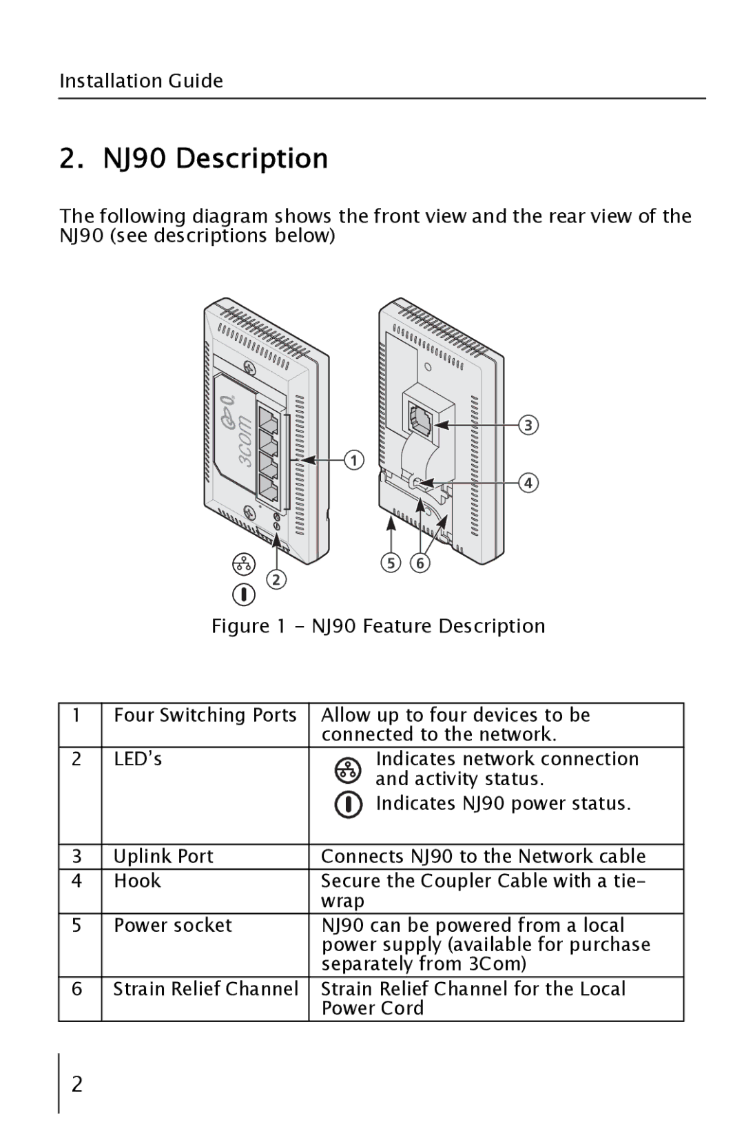
The following diagram shows the front view and the rear view of the NJ90 (see descriptions below)
3
1
4
5 | 6 |
2
Figure 1 - NJ90 Feature Description
1 | Four Switching Ports | Allow up to four devices to be |
|
| connected to the network. |
2 | LED’s | Indicates network connection |
|
| and activity status. |
|
| Indicates NJ90 power status. |
|
|
|
3 | Uplink Port | Connects NJ90 to the Network cable |
4 | Hook | Secure the Coupler Cable with a tie- |
|
| wrap |
5 | Power socket | NJ90 can be powered from a local |
|
| power supply (available for purchase |
|
| separately from 3Com) |
6 | Strain Relief Channel | Strain Relief Channel for the Local |
|
| Power Cord |
2