7 Checking the LED Indicators
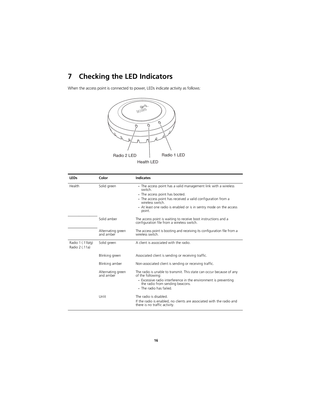
When the access point is connected to power, LEDs indicate activity as follows:
| Radio 2 LED | Radio 1 LED | |
|
| Health LED | |
|
|
| |
LEDs | Color | Indicates | |
|
|
|
|
Health | Solid green | • | The access point has a valid management link with a wireless |
|
|
| switch. |
|
| • | The access point has booted. |
|
| • | The access point has received a valid configuration from a |
|
|
| wireless switch. |
|
| • | At least one radio is enabled or is in sentry mode on the access |
|
|
| point. |
| Solid amber | The access point is waiting to receive boot instructions and a | |
| |||
|
| configuration file from a wireless switch. | |
| Alternating green | The access point is booting and receiving its configuration file from a | |
| |||
| and amber | wireless switch. | |
|
|
| |
Radio 1 (.11b/g) | Solid green | A client is associated with the radio. | |
Radio 2 (.11a) |
|
|
|
| Blinking green | Associated client is sending or receiving traffic. | |
| Blinking amber | ||
| Alternating green | The radio is unable to transmit. This state can occur because of any | |
| and amber | of the following: | |
|
| • | Excessive radio interference in the environment is preventing |
|
|
| the radio from sending beacons. |
|
| • | The radio has failed. |
| Unlit | The radio is disabled. | |
|
| If the radio is enabled, no clients are associated with the radio and | |
|
| there is no traffic activity. | |
|
|
|
|
16