COOKER HOB INSTALLATION
Important warnings
•Installation of the appliance and connection to the mains electricity must be carried out by qualified personnel only.
•The lining of the worktop walls must be suitably treated with adhesives capable of withstanding temperatures of 100°C (if not, the colour and shape of the lining may alter).
•The appliance must be fitted into the worktop on a cabinet at least 600 mm wide.
•After installing the hob, the two support elements secured on the
•All kitchen wall cabinets must be positioned so as to not hamper the user when operating the hob.
•The distance between the hob and cooker hood must comply with that indicated in the cooker hood installation instructions. The minimum distance must be 700 mm.
•Solid wood frames can be placed on the worktop provided they are positioned at a suitable distance (see picture).
•The minimum distance between the panel comprising the cooker hob and the rear wall is indicated in the picture.
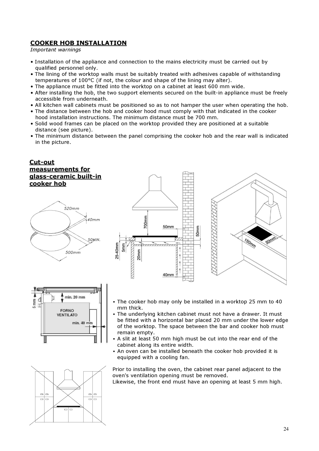
Cut-out measurements for glass-ceramic built-in cooker hob
▪The cooker hob may only be installed in a worktop 25 mm to 40 mm thick.
▪The underlying kitchen cabinet must not have a drawer. It must be fitted with a horizontal bar placed 20 mm under the lower edge of the worktop. The space between the bar and cooker hob must remain empty.
▪A slit at least 50 mm high must be cut into the rear end of the cabinet along its entire width.
▪An oven can be installed beneath the cooker hob provided it is equipped with a cooling fan.
Prior to installing the oven, the cabinet rear panel adjacent to the oven's ventilation opening must be removed.
Likewise, the front end must have an opening at least 5 mm high.
24