Installation and Set-Up (Continued)
4.Pneumatic Connection
The case former requires a 5.2 bar gauge pressure [75 PSIG], 6.0 m3/h @ 21°C, 1.01 bar [3.5 SCFM] compressed air supply.
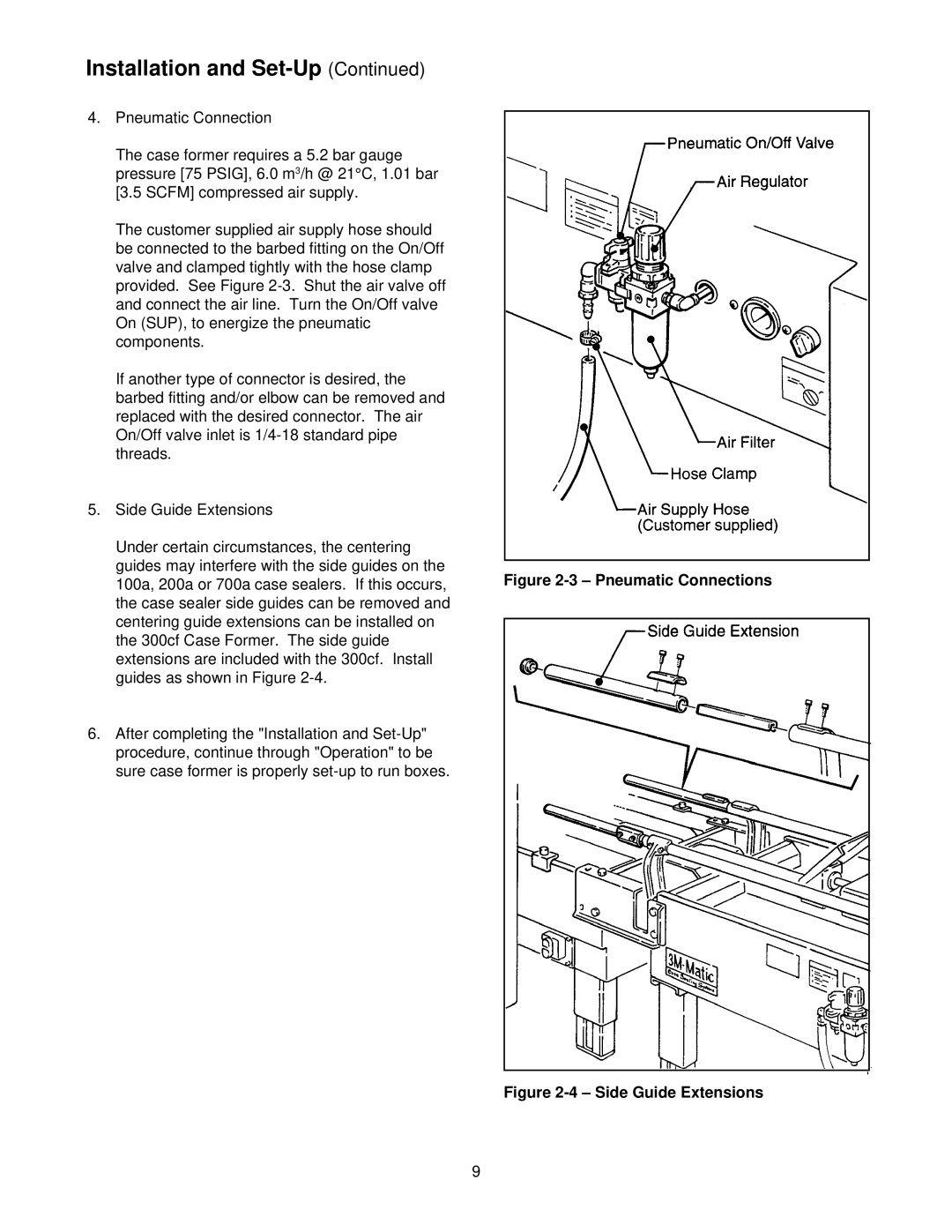
The customer supplied air supply hose should be connected to the barbed fitting on the On/Off valve and clamped tightly with the hose clamp provided. See Figure
If another type of connector is desired, the barbed fitting and/or elbow can be removed and replaced with the desired connector. The air On/Off valve inlet is
5.Side Guide Extensions
Under certain circumstances, the centering guides may interfere with the side guides on the 100a, 200a or 700a case sealers. If this occurs, the case sealer side guides can be removed and centering guide extensions can be installed on the 300cf Case Former. The side guide extensions are included with the 300cf. Install guides as shown in Figure
6.After completing the "Installation and
Figure 2-3 – Pneumatic Connections
Figure 2-4 – Side Guide Extensions
9
