Manuals
/
3M
/
Computer Equipment
/
Projector
3M
MP8625
manual
Models:
MP8625
1
2
36
36
Download
36 pages
54.8 Kb
1
2
3
4
5
6
7
8
Troubleshooting
Machine Characteristics
Example of computer signal
Factory Default Setting
Indicator Status
Warranty
Dimension
Maintenance
Accessories
Setup
Page 2
Image 2
Page 1
Page 3
Page 2
Image 2
Page 1
Page 3
Contents
MP8625 Multimedia Projector
Page
Table of Contents
English
Safeguards
Intended USE
Warranty
Limited Warranty
Unpack
Contents of Shipping Box
Optional Accessories
Keep Your Packaging Materials
Part Identification List
Machine Characteristics
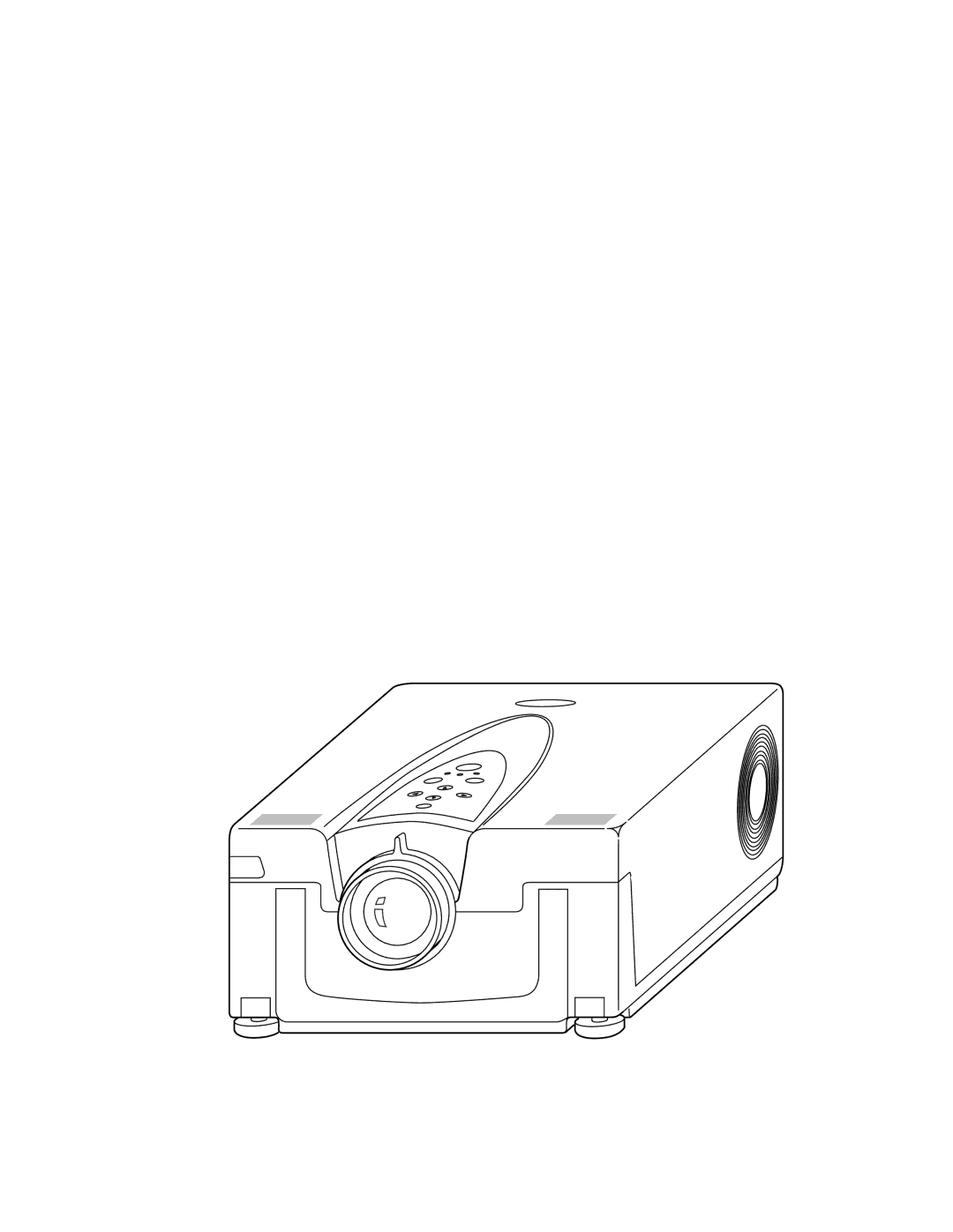
Product Description
System Set Up connecting various equipment
VCR
Remote Control Transmitter Identification
Laser Aperture
Projector Shutdown
Basic Operations
Projector Startup
Menu Navigation
Adjustment and Functions
Factory Default Setting
How To Use Height Adjustment Feet
Height Adjustment
Setup
Input
Image
Adjustment Value Default Screen
OPT
Maintenance
Cleaning the Air Filter
Display Lamp Operation Hours
Lamp
Lamp
Replacing the Lamp
Lamp Module
Message/Solution Table
Troubleshooting
Sympton/Solution Table
Accessories
Accessories
Service Information
How to Order
Technical Appendix
Table of Contents
Technical Specifications
Dimension
Projector-to-Screen Distance
Connection to the Video Signal Terminal
Connection to the RGB Signal Terminal
Example of computer signal
Indicator Status
Meaning Remedy
Connection to the Control Signal Terminal
Mouse emulation
RS-232 Control Cable not included with basic packout
Serial Command Codes
Serial Command Code Table
Serial Command Code Table
Technical
Page
3M Austin Center 3M Canada 3M Mexico, S.A. de C.V 3M Europe
Top
Page
Image
Contents