Section 5: Connection to Signal Terminals
5.1 Connection to the Video Signal Terminal
a.Input signal
Luminance signal | ||||
Chrominance signal | ||||
|
| |||
|
|
|
| |
VIDEO signal |
| |||
|
|
|
| |
AUDIO signal | Input |
| 200mVrms, 20 k Ω below (MAX | |
|
|
| ||
Output |
| 0~200mVrms, 1k Ω | ||
|
| |||
|
|
|
| |
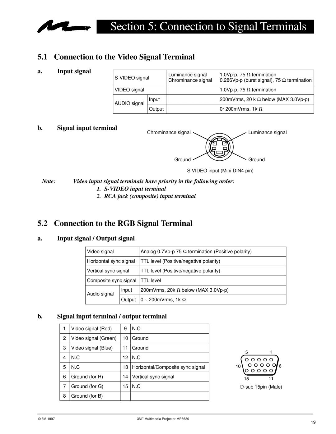
b.Signal input terminal
Chrominance signal | Luminance signal |
| Ground | Ground |
| S VIDEO input (Mini DIN4 pin) | |
Note: | Video input signal terminals have priority in the following order: |
|
1.
2.RCA jack (composite) input terminal
5.2Connection to the RGB Signal Terminal
a. | Input signal / Output signal |
| ||
|
|
|
|
|
|
| Video signal | Analog | |
|
|
|
|
|
|
| Horizontal sync signal | TTL level (Positive/negative polarity) | |
|
|
|
|
|
|
| Vertical sync signal | TTL level (Positive/negative polarity) | |
|
|
|
|
|
|
| Composite sync signal | TTL level | |
|
|
|
|
|
|
| Audio signal | Input | 200mVrms, 20k Ω below (MAX |
|
|
|
| |
|
| Output | 0 ∼ 200mVrms, 1k Ω | |
|
|
| ||
|
|
|
|
|
b.Signal input terminal / output terminal
1 | Video signal (Red) | 9 | N.C |
|
2 | Video signal (Green) | 10 | Ground |
|
3 | Video signal (Blue) | 11 | Ground |
|
4 | N.C | 12 | N.C |
|
5 | N.C | 13 | Horizontal/Composite sync signal |
|
6 | Ground (for R) | 14 | Vertical sync signal |
|
7 | Ground (for G) | 15 | N.C | |
8 | Ground (for B) |
|
|
|
© 3M 1997 |
|
| 3M™ Multimedia Projector MP8630 |
|
19