Installation
Hardware installation
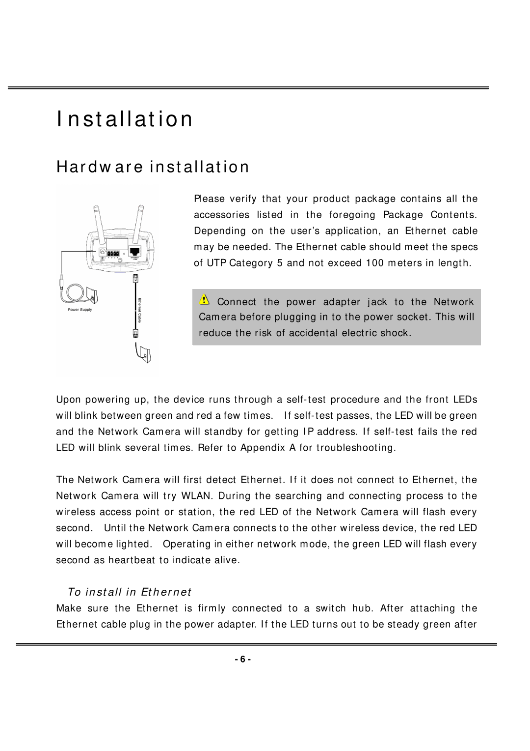
Please verify that your product package contains all the accessories listed in the foregoing Package Contents. Depending on the user’s application, an Ethernet cable may be needed. The Ethernet cable should meet the specs of UTP Category 5 and not exceed 100 meters in length.
![]() Connect the power adapter jack to the Network Camera before plugging in to the power socket. This will reduce the risk of accidental electric shock.
Connect the power adapter jack to the Network Camera before plugging in to the power socket. This will reduce the risk of accidental electric shock.
Upon powering up, the device runs through a
The Network Camera will first detect Ethernet. If it does not connect to Ethernet, the Network Camera will try WLAN. During the searching and connecting process to the wireless access point or station, the red LED of the Network Camera will flash every second. Until the Network Camera connects to the other wireless device, the red LED will become lighted. Operating in either network mode, the green LED will flash every second as heartbeat to indicate alive.
To install in Ethernet
Make sure the Ethernet is firmly connected to a switch hub. After attaching the Ethernet cable plug in the power adapter. If the LED turns out to be steady green after
- 6 -