internal signal routing, cont’d
Channels 5/6 input switch (P650 and P850) – selects input from three possibili- ties.
When the switch is in the left position, channels 5/6 receive input from the 5/6 DIN inputs.
When the switch is in the center position, channels 5/6 receive input from channels 1/2 RCA input.
When the switch is in the right position, channels 5/6 receive input from a summed input of channels 1, 2, 3, and 4 RCA input. Channel 5 receives the summed input of channels 1 and 3. Channel 6 receives the summed input of channels 2 and 4.
Channels 7/8 input switch (P850) – selects input from three possibilities.
When the switch is in the left position, channels 7/8 receive input from the 7/8 DIN inputs.
When the switch is in the center position, channels 7/8 receive input from channels 3/4 RCA input.
When the switch is in the right position, channels 7/8 receive input from a summed input of channels 1, 2, 3, and 4 RCA inut. Channel 7 receives the summed input of channels 1 and 3. Channel 8 receives the summed input of channels 2 and 4.
Level controls – Independent level controls for channels 1/2, 3/4, 5/6 and 7/8 adjust the input sensitivity from 90 mV to 5 VRMS.
Note: When crossover 3/4 output is selected for channels 1/2 and 3/4,
the 3/4 level control adjusts the output level for channels 1/2 and 3/4 simultaneously. When crossover 5/6 is selected for channels 5/6 and 7/8, the 5/6 level control adjusts the output level for channels 5/6 and 7/8 simultaneously.
Output –
nels can be configured in either stereo,
When the switch is in the left position, the output channels are configured for stereo operation.
When the switch is in the center position, the output channels are configured for summed mono bridged operation by mixing the left and right input signals together.
When the switch is in the right position, the output channels are configured for a
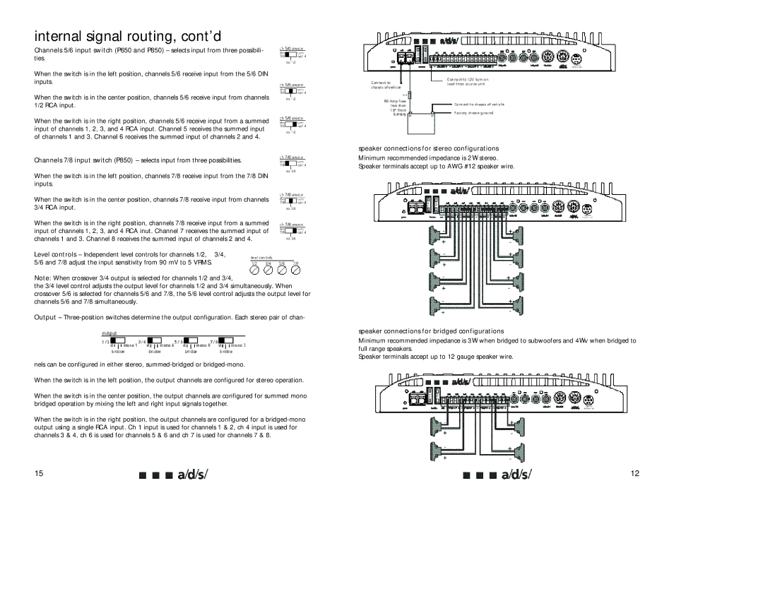
speaker connections for stereo configurations
Minimum recommended impedance is 2 W stereo.
Speaker terminals accept up to AWG #12 speaker wire.
speaker connections for bridged configurations
Minimum recommended impedance is 3W when bridged to subwoofers and 4Wv when bridged to full range speakers.
Speaker terminals accept up to 12 gauge speaker wire.
15 | 12 |
