Troubleshooting
symptom | possible cause | action to take |
no output | low or no remote | check remote |
|
| output at amplifier and correct |
|
| as needed |
| fuse blown | check power wire integrity |
|
| and reversed polarity, repair |
|
| as needed and replace fuse |
| power wires not connected | check power wire and ground |
|
| connections and repair or |
|
| replace as needed |
| audio input not connected or | check input connections and |
| no output from source | signal integrity, repair or |
|
| replace as needed |
| speaker wires not connected | check speaker wires and repair |
|
| or replace as needed |
audio cycles on and off | speakers are blown | check system with known |
|
| working speaker and repair or |
|
| replace speakers as needed |
system planning
Proper system planning is the best way to maximize your PowerPlateTM’s performance. By planning your installation carefully you can avoid situations where the performance or the reliability of your system is compromised. Your authorized a/d/s/ dealer has been trained to maximize your system’s sonic potential. Your a/d/s/ dealer is a valuable resource in helping you with your system design and installation.
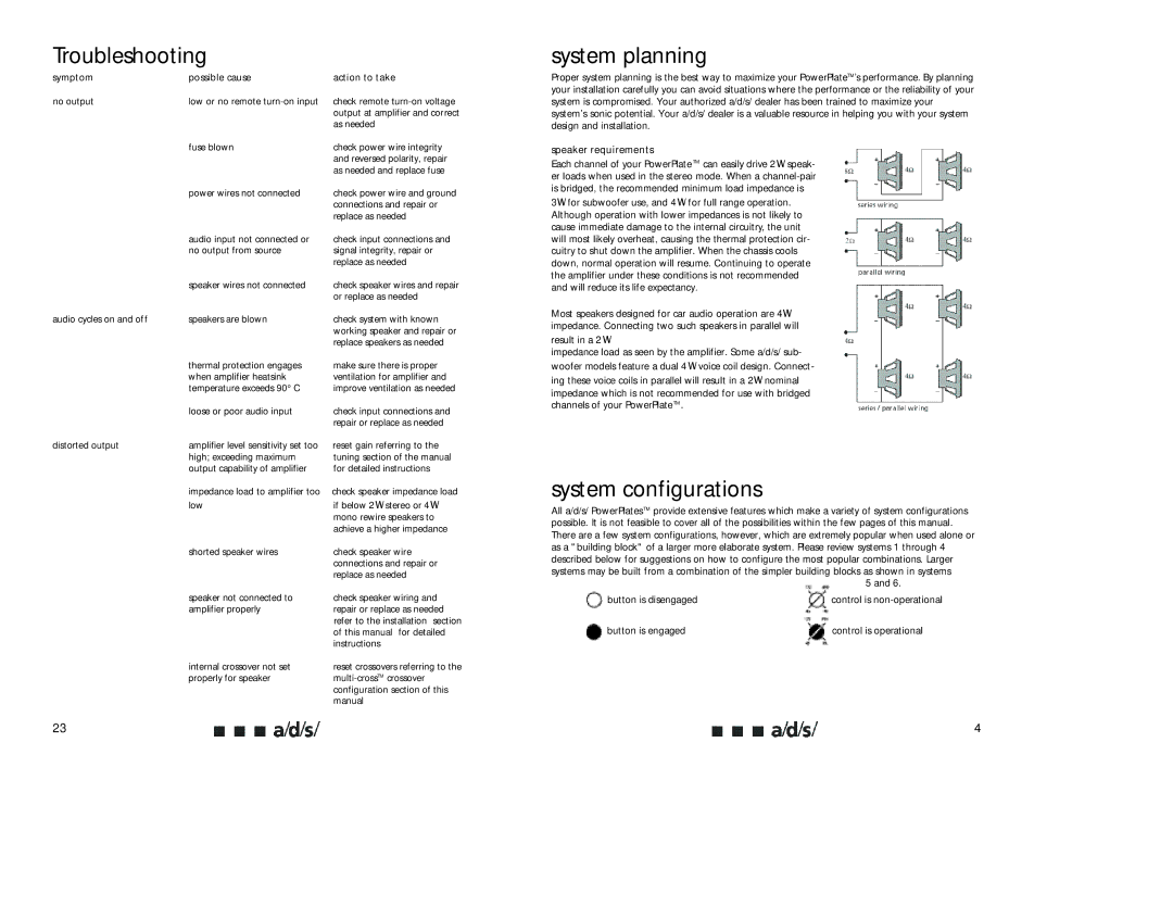
speaker requirements
Each channel of your PowerPlate TM can easily drive 2W speak- er loads when used in the stereo mode. When a
3W for subwoofer use, and 4W for full range operation. Although operation with lower impedances is not likely to cause immediate damage to the internal circuitry, the unit will most likely overheat, causing the thermal protection cir- cuitry to shut down the amplifier. When the chassis cools down, normal operation will resume. Continuing to operate the amplifier under these conditions is not recommended and will reduce its life expectancy.
Most speakers designed for car audio operation are 4W impedance. Connecting two such speakers in parallel will
result in a 2W
impedance load as seen by the amplifier. Some a/d/s/ sub-
| thermal protection engages |
| when amplifier heatsink |
| temperature exceeds 90° C |
| loose or poor audio input |
distorted output | amplifier level sensitivity set too |
| high; exceeding maximum |
| output capability of amplifier |
| impedance load to amplifier too |
| low |
make sure there is proper ventilation for amplifier and improve ventilation as needed
check input connections and repair or replace as needed
reset gain referring to the tuning section of the manual for detailed instructions
check speaker impedance load if below 2W stereo or 4W mono rewire speakers to achieve a higher impedance
woofer models feature a dual 4 W voice coil design. Connect- ing these voice coils in parallel will result in a 2W nominal impedance which is not recommended for use with bridged channels of your PowerPlateTM.
system configurations
All a/d/s/ PowerPlatesTM provide extensive features which make a variety of system configurations possible. It is not feasible to cover all of the possibilities within the few pages of this manual. There are a few system configurations, however, which are extremely popular when used alone or as a "building block" of a larger more elaborate system. Please review systems 1 through 4
shorted speaker wires | check speaker wire |
| connections and repair or |
| replace as needed |
speaker not connected to | check speaker wiring and |
amplifier properly | repair or replace as needed |
| refer to the installation section |
| of this manual for detailed |
| instructions |
internal crossover not set | reset crossovers referring to the |
properly for speaker | |
| configuration section of this |
| manual |
23
described below for suggestions on how to configure the most popular combinations. Larger systems may be built from a combination of the simpler building blocks as shown in systems
5 and 6.
button is disengaged |
| control is |
|
|
|
button is engaged |
| control is operational |
|
|
|
4