signal sources
Due to the wide input level adjustment range, all a/d/s/ PowerPlatesTM can be driven with either a conventional preamplifier drive signal or the amplified signal from a powered source unit. This makes the PowerPlateTM perfect for upgrading an OEM (Original Equipment Manufacturer) stereo system while retaining the factory installed radio.
Because of the high impedance of the a/d/s/ input stage, the factory radio drives an easy load. This ensures lower distortion levels than if it was driving speakers or a Line Output Converter accessory. As a result, a high quality factory installed radio can deliver high quality sound which is nearly as good as the sound from a
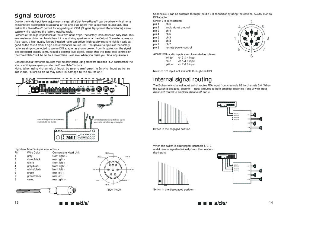
Conventional aftermarket sources may be connected using standard shielded RCA cables from the source unit’s preamp outputs to the PowerPlateTM inputs.
Note: When using 4 channels of input, be sure to configure the 2ch/4 ch input switch to 4ch input. Failure to do so may result in damage to the source unit.
Pin | Wire Color | Connects to Head Unit |
1 | gray | front right + |
2 | violet/black | rear right - |
3 | white | front left + |
4 | gray/black | front right - |
5 | white/black | front left - |
6 | green | rear left + |
7 | green/black | rear left - |
8 | violet | rear right + |
13
Channels
DIN ch
pin 1 | ch 6 |
pin 2 | audio signal ground |
pin 3 | ch 4 |
pin 4 | ch 5 |
pin 5 | ch 3 |
pin 6 | ch 8 |
pin 7 | ch 7 |
pin 8 | remote power control |
AC202 RCA audio inputs are color-coded as follows:
white | ch 3 & 4 input |
blue | ch 5 & 6 input |
yellow | ch 7 & 8 input |
Note: ch 1/2 input not available through the DIN.
internal signal routing
The
Switch in the engaged position.
When the switch is disengaged, channels 1, 2, 3, and 4 receive signal individually from their respec - tive inputs.
Switch in the disengaged position.
14