internal signal routing
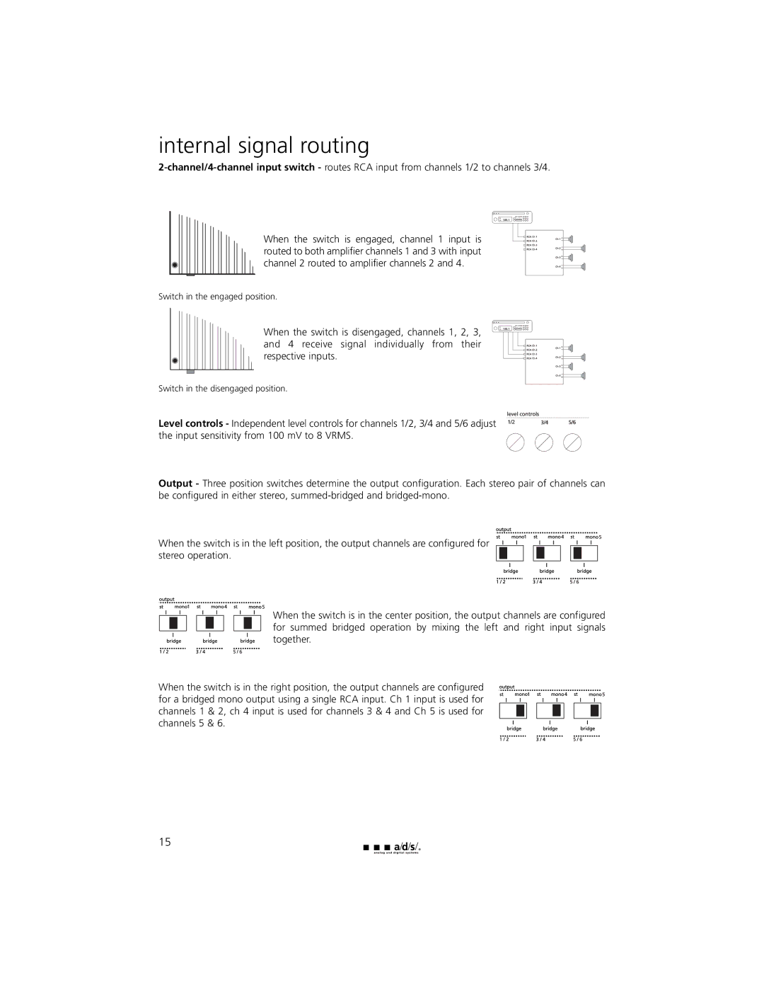
When the switch is engaged, channel 1 input is routed to both amplifier channels 1 and 3 with input channel 2 routed to amplifier channels 2 and 4.
Switch in the engaged position.
When the switch is disengaged, channels 1, 2, 3, and 4 receive signal individually from their respective inputs.
Switch in the disengaged position.
Level controls - Independent level controls for channels 1/2, 3/4 and 5/6 adjust the input sensitivity from 100 mV to 8 VRMS.
Output - Three position switches determine the output configuration. Each stereo pair of channels can be configured in either stereo,
When the switch is in the left position, the output channels are configured for stereo operation.
When the switch is in the center position, the output channels are configured for summed bridged operation by mixing the left and right input signals together.
When the switch is in the right position, the output channels are configured for a bridged mono output using a single RCA input. Ch 1 input is used for channels 1 & 2, ch 4 input is used for channels 3 & 4 and Ch 5 is used for channels 5 & 6.
15
