IMPORTANT

WHEN LOCATING THE TERMINALS ON A SIDEWALL, THE FOLLOWING

SPECIFICATIONS PERTAINING TO TERMINAL LOCATION MUST BE

FOLLOWED.

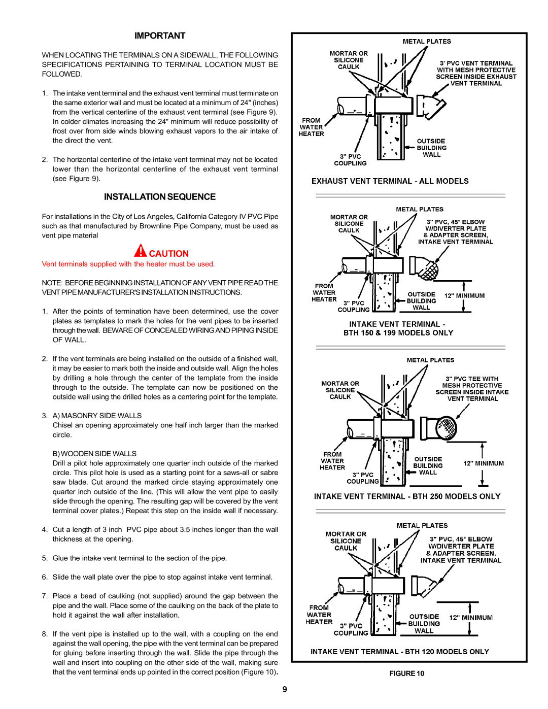
1.The intake vent terminal and the exhaust vent terminal must terminate on the same exterior wall and must be located at a minimum of 24" (inches) from the vertical centerline of the exhaust vent terminal (see Figure 9). In colder climates increasing the 24" minimum will reduce possibility of frost over from side winds blowing exhaust vapors to the air intake of the direct the vent.

2.The horizontal centerline of the intake vent terminal may not be located lower than the horizontal centerline of the exhaust vent terminal (see Figure 9).

INSTALLATION SEQUENCE

For installations in the City of Los Angeles, California Category IV PVC Pipe such as that manufactured by Brownline Pipe Company, must be used as vent pipe material

CAUTION

Vent terminals supplied with the heater must be used.

NOTE: BEFORE BEGINNING INSTALLATION OF ANY VENT PIPE READ THE

VENT PIPE MANUFACTURER'S INSTALLATION INSTRUCTIONS.

1.After the points of termination have been determined, use the cover plates as templates to mark the holes for the vent pipes to be inserted through the wall. BEWARE OF CONCEALED WIRING AND PIPING INSIDE OF WALL.

2.If the vent terminals are being installed on the outside of a finished wall, it may be easier to mark both the inside and outside wall. Align the holes by drilling a hole through the center of the template from the inside through to the outside. The template can now be positioned on the outside wall using the drilled holes as a centering point for the template.

3.A) MASONRY SIDE WALLS

Chisel an opening approximately one half inch larger than the marked circle.

B) WOODEN SIDE WALLS

Drill a pilot hole approximately one quarter inch outside of the marked circle. This pilot hole is used as a starting point for a saws-all or sabre saw blade. Cut around the marked circle staying approximately one quarter inch outside of the line. (This will allow the vent pipe to easily slide through the opening. The resulting gap will be covered by the vent terminal cover plates.) Repeat this step on the inside wall if necessary.

4.Cut a length of 3 inch PVC pipe about 3.5 inches longer than the wall thickness at the opening.

5.Glue the intake vent terminal to the section of the pipe.

6.Slide the wall plate over the pipe to stop against intake vent terminal.

7.Place a bead of caulking (not supplied) around the gap between the pipe and the wall. Place some of the caulking on the back of the plate to hold it against the wall after installation.

8.If the vent pipe is installed up to the wall, with a coupling on the end against the wall opening, the pipe with the vent terminal can be prepared for gluing before inserting through the wall. Slide the pipe through the wall and insert into coupling on the other side of the wall, making sure

that the vent terminal ends up pointed in the correct position (Figure 10).

FIGURE 10

9

Page 9
Image 9
A.O. Smith BTH 120 - 250 Installation Sequence, Vent Pipe Manufacturers Installation Instructions, Masonry Side Walls

BTH 120 - 250 specifications

The A.O. Smith BTH 120 - 250 is a high-efficiency water heater designed for commercial and industrial applications, renowned for its advanced technology and durable construction. This model stands out for its ability to provide reliable hot water while minimizing energy consumption, making it an ideal choice for businesses looking to enhance operational efficiency.

One of the main features of the A.O. Smith BTH series is its innovative design that integrates cutting-edge condensing technology. This system maximizes energy use by capturing and reusing heat that would otherwise be lost in traditional water heating methods. As a result, the BTH 120 - 250 delivers exceptional thermal efficiency ratings, often exceeding 90%, thereby reducing overall operating costs.

The BTH series is available in various capacities, ranging from 120,000 to 250,000 BTU per hour, ensuring that it meets the diverse needs of different businesses. This flexibility allows for installation in a variety of settings, from small restaurants to large manufacturing facilities.

Another significant characteristic of the BTH 120 - 250 is its robust construction. Built with high-quality materials, this unit is designed to withstand the rigors of continuous use. Its stainless steel heat exchanger resists corrosion and scale build-up, providing longevity and reduced maintenance requirements.

Safety features are integrated into the BTH series as well. It includes an electronic ignition system that eliminates the need for a standing pilot light, enhancing operational safety and reducing energy waste. Additionally, the built-in diagnostic system allows for quick identification of issues, streamlining maintenance procedures.

The BTH series also emphasizes user-friendly operation. Equipped with advanced control options, operators can monitor and adjust performance settings effortlessly. The digital display provides real-time operational data, which can assist in optimizing performance and ensuring consistent hot water availability.

In summary, the A.O. Smith BTH 120 - 250 is an exceptional choice for commercial water heating, combining high efficiency, advanced technology, and robust durability. Its innovative design, safety features, and user-friendly controls position it as a trusted solution for businesses seeking reliable hot water systems. By investing in this model, operators can ensure optimal performance while enjoying significant energy savings over time.