IMPORTANT

The vent system must terminate so that proper clearances are maintained as cited in local codes or the latest edition of the National Fuel Gas Code, ANSI Z223.1,7.3.4e and 7.8a,b, as follows:

1.Do not terminate the exhaust vent terminal over public area where condensate or vapor can cause nuisance or hazard.

2.For direct vent, the venting system shall terminate at least 1 foot below, 1 foot horizontally from or 1 foot above any door, window, or gravity air inlet into building.

3.For horizontal the venting system shall terminate 4 foot below, 4 foot horizontally from or 1 foot above any door, window, or gravity air inlet into building.

4.The manufacturer also recommends the vent system terminations not be installed closer than 3 feet from an inside corner of an L shaped structure. And not less than 1 foot above grade or anticipated snow level.

5.The vent termination shall not be mounted directly above or within 3 feet horizontally from an oil tank vent or gas meter to avoid potential freeze- up from condensation.

6.The vent shall terminate a minimum of 12" above expected snowfall level to prevent blockage of vent termination.

Plan the vent system layout so that proper clearances are maintained from plumbing and wiring.

Vent pipes serving power vented appliances are classified by building codes as "vent connectors". Required clearances from combustible materials must be provided in accordance with information in this manual under LOCATION OF HEATER and CLEARANCES, and with National Fuel Gas Code and local Codes.

IMPORTANT

Plan the layout of the vent system backwards from the vent termination to the appliance.

WARNING

USEONLYTHEVENTTERMINALSSUPPLIEDWITHTHISUNIT.TERMINATION OF A VENT SYSTEM WITH A DEVICE OTHER THAN THE SUPPLIED VENT TERMINATIONS WILL AFFECT SYSTEM PERFORMANCE AND RESULT IN A SAFETY HAZARD.

DIRECT VENTING

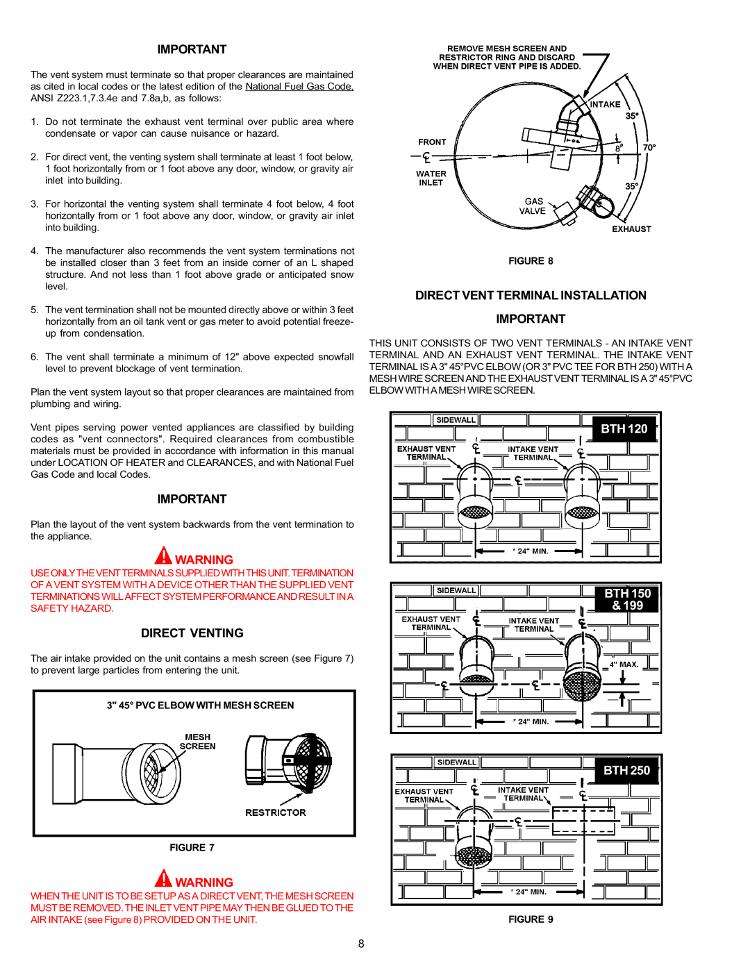
The air intake provided on the unit contains a mesh screen (see Figure 7) to prevent large particles from entering the unit.

3" 45° PVC ELBOW WITH MESH SCREEN

FIGURE 7

WARNING

WHEN THE UNIT IS TO BE SETUP AS A DIRECT VENT, THE MESH SCREEN MUST BE REMOVED. THE INLET VENT PIPE MAY THEN BE GLUED TO THE AIR INTAKE (see Figure 8) PROVIDED ON THE UNIT.

FIGURE 8

DIRECT VENT TERMINAL INSTALLATION

IMPORTANT

THIS UNIT CONSISTS OF TWO VENT TERMINALS - AN INTAKE VENT TERMINAL AND AN EXHAUST VENT TERMINAL. THE INTAKE VENT TERMINAL IS A 3" 45°PVC ELBOW (OR 3" PVC TEE FOR BTH 250) WITH A MESH WIRE SCREEN AND THE EXHAUST VENT TERMINAL IS A 3" 45°PVC ELBOW WITH A MESH WIRE SCREEN.

BTH 120

BTH 150

& 199

BTH 250

FIGURE 9

8

Page 8
Image 8
A.O. Smith BTH 120 - 250 warranty Direct Venting, Direct Vent Terminal Installation, PVC Elbow with Mesh Screen

BTH 120 - 250 specifications

The A.O. Smith BTH 120 - 250 is a high-efficiency water heater designed for commercial and industrial applications, renowned for its advanced technology and durable construction. This model stands out for its ability to provide reliable hot water while minimizing energy consumption, making it an ideal choice for businesses looking to enhance operational efficiency.

One of the main features of the A.O. Smith BTH series is its innovative design that integrates cutting-edge condensing technology. This system maximizes energy use by capturing and reusing heat that would otherwise be lost in traditional water heating methods. As a result, the BTH 120 - 250 delivers exceptional thermal efficiency ratings, often exceeding 90%, thereby reducing overall operating costs.

The BTH series is available in various capacities, ranging from 120,000 to 250,000 BTU per hour, ensuring that it meets the diverse needs of different businesses. This flexibility allows for installation in a variety of settings, from small restaurants to large manufacturing facilities.

Another significant characteristic of the BTH 120 - 250 is its robust construction. Built with high-quality materials, this unit is designed to withstand the rigors of continuous use. Its stainless steel heat exchanger resists corrosion and scale build-up, providing longevity and reduced maintenance requirements.

Safety features are integrated into the BTH series as well. It includes an electronic ignition system that eliminates the need for a standing pilot light, enhancing operational safety and reducing energy waste. Additionally, the built-in diagnostic system allows for quick identification of issues, streamlining maintenance procedures.

The BTH series also emphasizes user-friendly operation. Equipped with advanced control options, operators can monitor and adjust performance settings effortlessly. The digital display provides real-time operational data, which can assist in optimizing performance and ensuring consistent hot water availability.

In summary, the A.O. Smith BTH 120 - 250 is an exceptional choice for commercial water heating, combining high efficiency, advanced technology, and robust durability. Its innovative design, safety features, and user-friendly controls position it as a trusted solution for businesses seeking reliable hot water systems. By investing in this model, operators can ensure optimal performance while enjoying significant energy savings over time.