tubing must be connected in order for the switch to change the electrical contacts. The controller requires that the electrical contacts on this air flow switch be open before it will allow the blower to come on.
BLOCKED OUTLET PROVER SWITCH
(SEE FIGURE 13)
The Blocked Outlet Prover Switch is set up to shut the unit off when a build- up of positive pressure in the exhaust vent pipe occurs. This switch is a positive pressure switch that requires an increase in pressure to change the electrical contacts from normally closed to open. When this switch prevents the unit from igniting, most likely the exhaust is blocked by some means Check to see if the condensate is allowed to flow freely from the exhaust elbow and for obstructions in the exhaust venting and exhaust vent terminal. Also verify that there is no more than fifty equivalent feet of three inch PVC vent pipe on the exhaust.
BLOCKED INLET PROVER SWITCH
(SEE FIGURE 13)
The Blocked Inlet Prover Switch is set up to shut the unit off when a build- up of negative pressure in the intake vent pipe occurs. This switch is a negative pressure switch that requires an increase in negative pressure to change the electrical contacts from normally closed to open. The switch is connected to the pressure tap on the PVC flange connected to the inlet of the blower. When this switch prevents the unit from igniting, most likely the intake is blocked by some means. Check to see if there is no more than fifty equivalent feet of three inch PVC vent pipe on the intake. Also verify that the intake and intake vent terminal is free of obstructions that may prevent air from entering the unit.
LOW GAS PRESSURE SWITCH
(SEE FIGURE 13)
The Low Gas Switch (LGS) is a single-pole, normally open pressure switch that will close its contacts when a rising pressure of 5.0 in. W.C. is encountered. The contacts will open when the pressure falls below the fixed set point of 5.0 in. W.C. The LGS monitors the gas supply pressure to the heater. If the gas supply falls below 5.0 in. W.C., the main burner is extinguished (if heater is running) or the heater will not start up.
ON/OFF SWITCH
The ON/OFF Switch is a single-pole, single-throw rocker switch. This switch provides 120V from the line source to the heater.
 CAUTION
THE WATER HEATER IS POLARITY SENSITIVE. BEFORE APPLYING ELECTRICITYTOTHISHEATERBECERTAINTHATSUPPLYNEUTRALWIRE TO GROUND CHECK INDICATES ZERO VOLTAGE.
HOT SURFACE IGNITER
The Hot Surface Igniter is a device that ignites the main burner by high temperature (>1800°F). When 120VAC is applied to the igniter, sufficient heat is generated to ignite the main burner. Although improvements have been made to strengthen the igniter, it is still fragile and care must be taken when handling the igniter to prevent breakage.
GAS PIPING
Contact your local gas service company to ensure that adequate gas service is available and to review applicable installation codes for your area.
Size the main gas line in accordance with Table 3. The figures shown are for straight lengths of pipe at 0.5 in. W.C. pressure drop, which is considered normal for low pressure systems Note that fittings such as elbows and tees will add to the pipe pressure drop.
 CAUTION
DO NOT USE FLEXIBLE GAS PIPING.
TABLE 3
MAXIMUM CAPACITY OF PIPE
IN CUBIC FEET OF GAS PER HOUR
(Based upon a Pressure Drop of 0.5 inch Water Column
and 0.6 Specific Gravity Gas and max. gas pressure of 0.5 psig)
Length | | | | NOMINAL IRON PIPE SIZES, INCHES | |
| | | | | | | | | | |
in Feet | 1/2" | 3/4" | 1" | | 1 1/4" | 1 1/2" | 2" | 2 1/2" | 3" | 4" |
10 | 175 | 360 | 680 | | 1,400 | 2,100 | 3,950 | 6,300 | 11,000 | 23,000 |
| | | | | | | | | | |
20 | 120 | 250 | 465 | | 950 | 1,460 | 2,750 | 4,350 | 7,700 | 15,800 |
30 | 97 | 200 | 375 | | 770 | 1,180 | 2,200 | 3,520 | 6,250 | 12,800 |
40 | 82 | 170 | 320 | | 660 | 990 | 1,900 | 3,000 | 5,300 | 10,900 |
| | | | | | | | | | |
50 | 73 | 151 | 285 | | 580 | 900 | 1,680 | 2,650 | 4,750 | 9,700 |
60 | 66 | 138 | 260 | | 530 | 810 | 1,520 | 2,400 | 4,300 | 8,800 |
70 | 61 | 125 | 240 | | 490 | 750 | 1,400 | 2,250 | 3,900 | 8,100 |
| | | | | | | | | | |
80 | 57 | 118 | 220 | | 460 | 690 | 1,300 | 2,050 | 3,700 | 7,500 |
90 | 53 | 110 | 205 | | 430 | 650 | 1,220 | 1,950 | 3,450 | 7,200 |
100 | 50 | 103 | 195 | | 400 | 620 | 1,150 | 1,850 | 3,250 | 6,700 |
| | | | | | | | | | |
125 | 44 | 93 | 175 | | 360 | 550 | 1,020 | 1,650 | 2,950 | 6,000 |
150 | 40 | 84 | 160 | | 325 | 500 | 950 | 1,500 | 2,650 | 5,500 |
175 | 37 | 377 | 145 | | 300 | 460 | 850 | 1,370 | 2,450 | 5,000 |
| | | | | | | | | | |
200 | 36 | 72 | 135 | | 280 | 430 | 800 | 1,280 | 2,280 | 4,600 |
 WARNING
THE HEATER IS NOT INTENDED FOR OPERATION AT HIGHER THAN 14.0" WATERCOLUMN(1/2POUNDPERSQUAREINCH)SUPPLYGASPRESSURE. HIGHER GASSUPPLYPRESSURESREQUIRESUPPLEMENTALREDUCING SERVICE REGULATION. EXPOSURE TO HIGHER GAS SUPPLY PRESSURE MAY CAUSE DAMAGE TO THE GAS CONTROLS WHICH COULD RESULT IN FIRE OR EXPLOSION. IF OVERPRESSURE HAS OCCURRED SUCH AS THROUGH IMPROPER TESTING OF GAS LINES OR EMERGENCY MALFUNCTION OF THE SUPPLY SYSTEM THE GAS VALVE MUST BE CHECKEDFORSAFEOPERATION.MAKESURETHATTHEOUTSIDEVENTS ON THE SUPPLY REGULATORS AND THE SAFETY VENT VALVES ARE PROTECTED AGAINST BLOCKAGE. THESE ARE PARTS OF THE GAS SUPPLY SYSTEM, NOT THE HEATER. VENT BLOCKAGE MAY OCCUR DURINGICESTORMS.
IT IS IMPORTANT TO GUARD AGAINST GAS VALVE FOULING FROM CONTAMINANTS IN THE GAS WAYS. SUCH FOULING MAY CAUSE IMPROPEROPERATION,FIREOREXPLOSION.
IFCOPPERSUPPLYLINESAREUSEDTHEYMUSTBEINTERNALLYTINNED AND CERTIFIED FOR GAS SERVICE.
BEFORE ATTACHING THE GAS LINE BE SURE THAT ALL GAS PIPE IS CLEAN ON THE INSIDE.
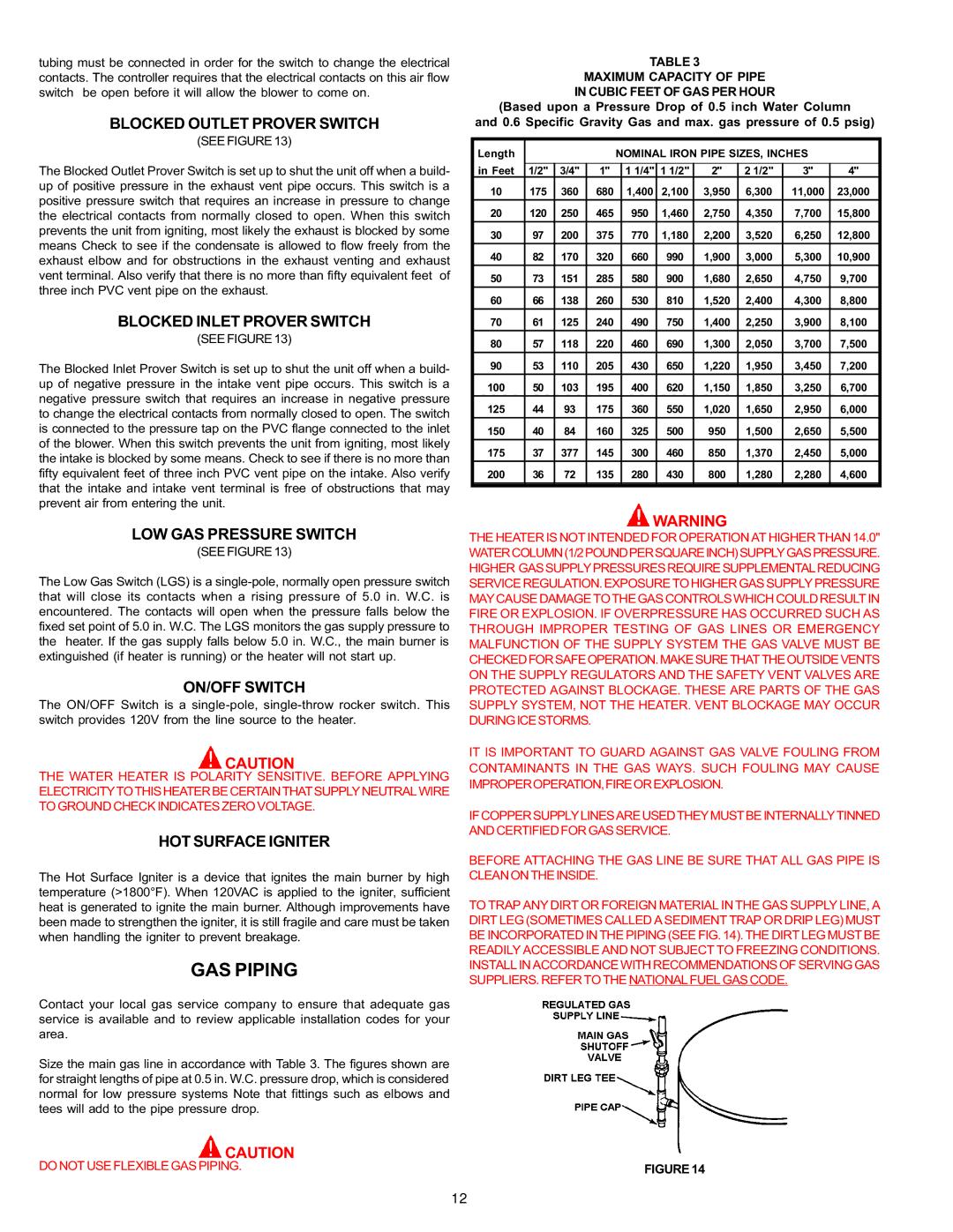
TO TRAP ANY DIRT OR FOREIGN MATERIAL IN THE GAS SUPPLY LINE, A DIRT LEG (SOMETIMES CALLED A SEDIMENT TRAP OR DRIP LEG) MUST BE INCORPORATED IN THE PIPING (SEE FIG. 14). THE DIRT LEG MUST BE READILY ACCESSIBLE AND NOT SUBJECT TO FREEZING CONDITIONS. INSTALL IN ACCORDANCE WITH RECOMMENDATIONS OF SERVING GAS SUPPLIERS. REFER TO THE NATIONAL FUEL GAS CODE.
FIGURE 14