A.O. Smith BTH 120-250(A) Vertical Vent Terminal Installation, Installation of Vent System

Models: BTH 120-250(A)

1 32
Download 32 pages 59.1 Kb
Page 10
Image 10

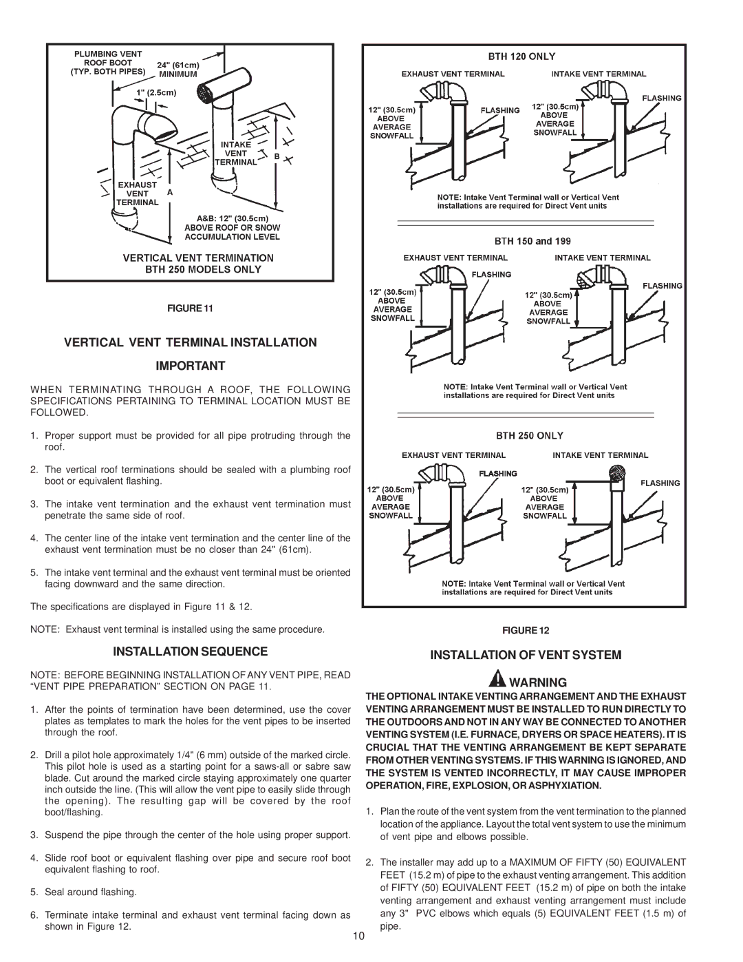
FIGURE 11

VERTICAL VENT TERMINAL INSTALLATION

IMPORTANT

WHEN TERMINATING THROUGH A ROOF, THE FOLLOWING

SPECIFICATIONS PERTAINING TO TERMINAL LOCATION MUST BE

FOLLOWED.

1.Proper support must be provided for all pipe protruding through the roof.

2.The vertical roof terminations should be sealed with a plumbing roof boot or equivalent flashing.

3.The intake vent termination and the exhaust vent termination must penetrate the same side of roof.

4.The center line of the intake vent termination and the center line of the exhaust vent termination must be no closer than 24" (61cm).

5.The intake vent terminal and the exhaust vent terminal must be oriented facing downward and the same direction.

The specifications are displayed in Figure 11 & 12.

NOTE: Exhaust vent terminal is installed using the same procedure.

FIGURE 12

INSTALLATION SEQUENCE

NOTE: BEFORE BEGINNING INSTALLATION OF ANY VENT PIPE, READ “VENT PIPE PREPARATION” SECTION ON PAGE 11.

1.After the points of termination have been determined, use the cover plates as templates to mark the holes for the vent pipes to be inserted through the roof.

2.Drill a pilot hole approximately 1/4" (6 mm) outside of the marked circle. This pilot hole is used as a starting point for a saws-all or sabre saw blade. Cut around the marked circle staying approximately one quarter inch outside the line. (This will allow the vent pipe to easily slide through the opening). The resulting gap will be covered by the roof boot/flashing.

3.Suspend the pipe through the center of the hole using proper support.

4.Slide roof boot or equivalent flashing over pipe and secure roof boot equivalent flashing to roof.

5.Seal around flashing.

6.Terminate intake terminal and exhaust vent terminal facing down as shown in Figure 12.

INSTALLATION OF VENT SYSTEM

WARNING

THE OPTIONAL INTAKE VENTING ARRANGEMENT AND THE EXHAUST VENTING ARRANGEMENT MUST BE INSTALLED TO RUN DIRECTLY TO THE OUTDOORS AND NOT IN ANY WAY BE CONNECTED TO ANOTHER VENTING SYSTEM (I.E. FURNACE, DRYERS OR SPACE HEATERS). IT IS CRUCIAL THAT THE VENTING ARRANGEMENT BE KEPT SEPARATE FROM OTHER VENTING SYSTEMS. IF THIS WARNING IS IGNORED, AND THE SYSTEM IS VENTED INCORRECTLY, IT MAY CAUSE IMPROPER OPERATION, FIRE, EXPLOSION, OR ASPHYXIATION.

1.Plan the route of the vent system from the vent termination to the planned location of the appliance. Layout the total vent system to use the minimum of vent pipe and elbows possible.

2.The installer may add up to a MAXIMUM OF FIFTY (50) EQUIVALENT FEET (15.2 m) of pipe to the exhaust venting arrangement. This addition of FIFTY (50) EQUIVALENT FEET (15.2 m) of pipe on both the intake venting arrangement and exhaust venting arrangement must include any 3" PVC elbows which equals (5) EQUIVALENT FEET (1.5 m) of pipe.

10

Page 10
Image 10
A.O. Smith BTH 120-250(A) warranty Vertical Vent Terminal Installation, Installation of Vent System

BTH 120-250(A) specifications

A.O. Smith BTH 120-250(A) is a cutting-edge water heater designed to meet the demands of residential and commercial settings. This high-efficiency unit is equipped with a range of features aimed at maximizing performance and minimizing energy consumption, making it a popular choice among homeowners and builders alike.

One of the standout features of the A.O. Smith BTH 120-250(A) is its energy efficiency. It operates with a thermal efficiency rating of up to 96%, which means that a significant portion of the fuel consumed is converted into usable hot water. This not only reduces energy bills but also lessens the environmental impact of water heating.

The unit employs advanced condensing technology, which captures and utilizes the heat from flue gases that would otherwise be lost in traditional units. This technology allows for lower exhaust temperatures and the potential for venting through PVC, significantly simplifying installation in various settings.

With a capacity range of 120 to 250 gallons, the BTH series is versatile enough to serve different needs. It is suitable for multiple applications, including large residential homes, commercial businesses, and industrial installations. The varying sizes ensure that it can deliver adequate hot water supply, even during peak demand periods.

In addition to its impressive capacity and efficiency, the A.O. Smith BTH 120-250(A) features a user-friendly digital control system. This allows users to easily set and monitor water temperatures, helping to prevent scalding and ensuring consistent comfort. The integrated diagnostics system alerts users to potential issues, facilitating proactive maintenance and reducing downtime.

Another appealing characteristic of this water heater is its durable construction. Built with high-quality materials, it is designed to withstand the rigors of frequent use while maintaining optimal performance over time. Furthermore, it comes equipped with an innovative flame rollback feature, enhancing safety by reducing the risk of flashback.

Overall, the A.O. Smith BTH 120-250(A) stands out in the competitive water heater market due to its exceptional efficiency, advanced technologies, and robust construction. Whether for residential or commercial use, this model provides reliable hot water supply while promoting energy savings and environmental sustainability. Its combination of performance and user-friendly features makes it a top choice for those seeking a reliable water heating solution.