TRANSMITTED INTO THE LIVING SPACES.

IMPORTANT

The vent system must terminate so that proper clearances are maintained as cited in local codes or the latest edition of the National Fuel Gas Code, ANSI Z223.1/NFPA 54 and for Canadian installations consult the Canadian Installation Codes and CAN/CGA B149.1 and .2.

1.Do not terminate the exhaust vent terminal over public area where condensate or vapor can cause nuisance or hazard.

2.For direct vent, the venting system shall terminate at least 1' (30.5 cm) below, 1' (30.5 cm) horizontally from or 1' (30.5 cm) above any door, window, or gravity air inlet into building.

3.For horizontal the venting system, using room for combustion, the vent terminal shall terminate 4' (122 cm) below, 4' (122 cm) horizontally from or 1' (30.5 cm) above any door, window, or gravity air inlet into building.

4.The manufacturer also recommends the vent system terminations not be installed closer than 3' (91cm) from an inside corner of an L shaped structure. And not less than 1' (30.5 cm) above grade or anticipated snow level.

5.The vent termination shall not be mounted directly above or within 3' (91cm) horizontally from an oil tank vent or gas meter to avoid potential freeze-up from condensation.

6.The vent shall terminate a minimum of 12" (30.5 cm) above expected snowfall level to prevent blockage of vent termination.

Plan the vent system layout so that proper clearances are maintained from plumbing and wiring.

Vent pipes serving power vented appliances are classified by building codes as "vent connectors". Required clearances from combustible materials must be provided in accordance with information in this manual under LOCATION OF HEATER and CLEARANCES, and with National Fuel Gas Code and local Codes.

IMPORTANT

Plan the layout of the vent system backwards from the vent termination to the appliance.

WARNING

USE ONLY THE VENT TERMINALS SUPPLIED WITH THIS UNIT. TERMINATION OF A VENT SYSTEM WITH A DEVICE OTHER THAN THE SUPPLIED VENT TERMINATIONS WILL AFFECT SYSTEM PERFORMANCE AND RESULT IN A SAFETY HAZARD.

DIRECT VENTING

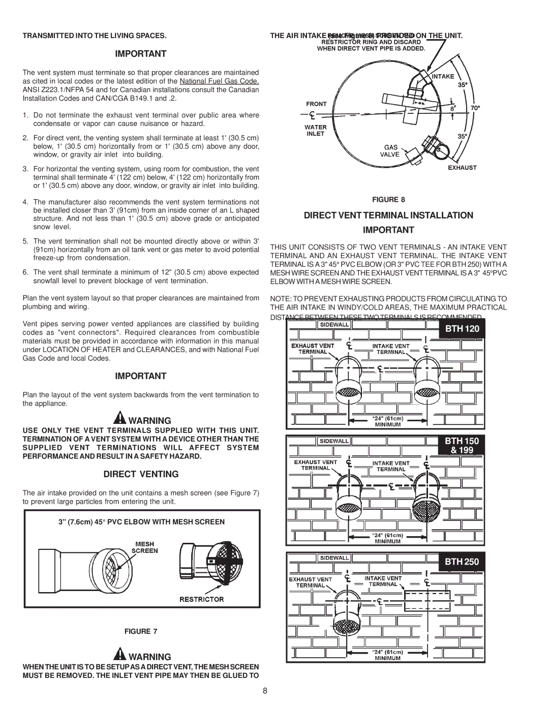
The air intake provided on the unit contains a mesh screen (see Figure 7) to prevent large particles from entering the unit.

3" (7.6cm) 45° PVC ELBOW WITH MESH SCREEN

FIGURE 7

WARNING

WHEN THE UNIT IS TO BE SETUPAS A DIRECT VENT, THE MESH SCREEN MUST BE REMOVED. THE INLET VENT PIPE MAY THEN BE GLUED TO

THE AIR INTAKE (see Figure 8) PROVIDED ON THE UNIT.

FIGURE 8

DIRECT VENT TERMINAL INSTALLATION

IMPORTANT

THIS UNIT CONSISTS OF TWO VENT TERMINALS - AN INTAKE VENT TERMINAL AND AN EXHAUST VENT TERMINAL. THE INTAKE VENT TERMINAL IS A 3" 45° PVC ELBOW (OR 3" PVC TEE FOR BTH 250) WITH A MESH WIRE SCREEN AND THE EXHAUST VENT TERMINAL IS A 3" 45°PVC ELBOW WITH A MESH WIRE SCREEN.

NOTE: TO PREVENT EXHAUSTING PRODUCTS FROM CIRCULATING TO THE AIR INTAKE IN WINDY/COLD AREAS, THE MAXIMUM PRACTICAL

DISTANCE BETWEEN THESE TWO TERMINALS IS RECOMMENDED.

BTH 120

BTH 150

& 199

BTH 250

8

Page 8
Image 8
A.O. Smith BTH 120-250(A) warranty Direct Venting, Direct Vent Terminal Installation, Transmitted Into the Living Spaces

BTH 120-250(A) specifications

A.O. Smith BTH 120-250(A) is a cutting-edge water heater designed to meet the demands of residential and commercial settings. This high-efficiency unit is equipped with a range of features aimed at maximizing performance and minimizing energy consumption, making it a popular choice among homeowners and builders alike.

One of the standout features of the A.O. Smith BTH 120-250(A) is its energy efficiency. It operates with a thermal efficiency rating of up to 96%, which means that a significant portion of the fuel consumed is converted into usable hot water. This not only reduces energy bills but also lessens the environmental impact of water heating.

The unit employs advanced condensing technology, which captures and utilizes the heat from flue gases that would otherwise be lost in traditional units. This technology allows for lower exhaust temperatures and the potential for venting through PVC, significantly simplifying installation in various settings.

With a capacity range of 120 to 250 gallons, the BTH series is versatile enough to serve different needs. It is suitable for multiple applications, including large residential homes, commercial businesses, and industrial installations. The varying sizes ensure that it can deliver adequate hot water supply, even during peak demand periods.

In addition to its impressive capacity and efficiency, the A.O. Smith BTH 120-250(A) features a user-friendly digital control system. This allows users to easily set and monitor water temperatures, helping to prevent scalding and ensuring consistent comfort. The integrated diagnostics system alerts users to potential issues, facilitating proactive maintenance and reducing downtime.

Another appealing characteristic of this water heater is its durable construction. Built with high-quality materials, it is designed to withstand the rigors of frequent use while maintaining optimal performance over time. Furthermore, it comes equipped with an innovative flame rollback feature, enhancing safety by reducing the risk of flashback.

Overall, the A.O. Smith BTH 120-250(A) stands out in the competitive water heater market due to its exceptional efficiency, advanced technologies, and robust construction. Whether for residential or commercial use, this model provides reliable hot water supply while promoting energy savings and environmental sustainability. Its combination of performance and user-friendly features makes it a top choice for those seeking a reliable water heating solution.