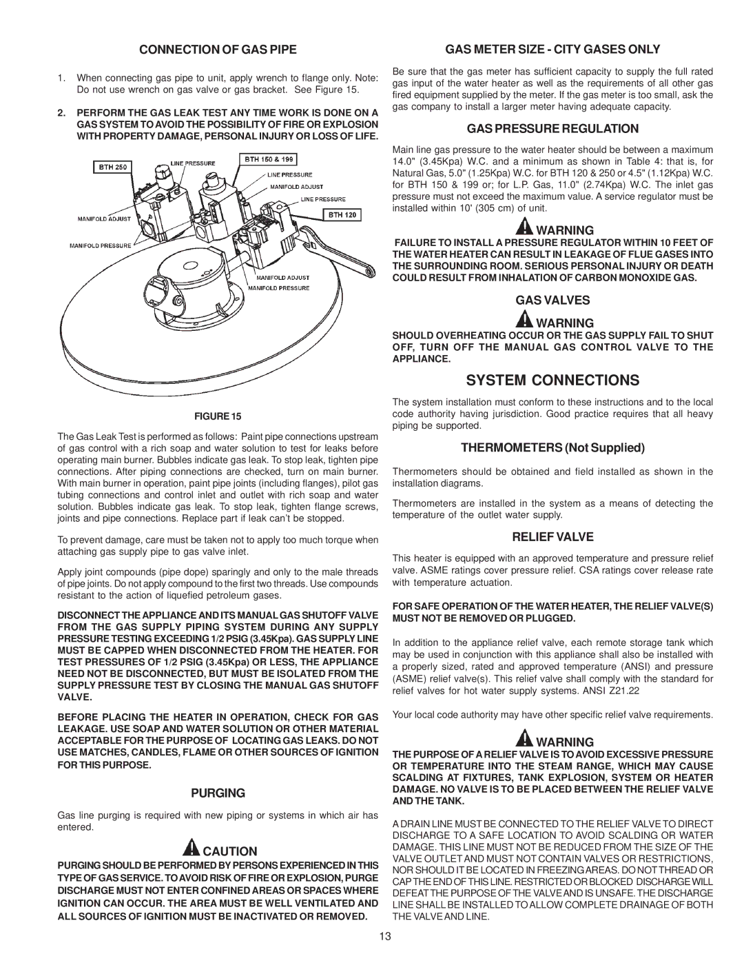
1.When connecting gas pipe to unit, apply wrench to flange only. Note: Do not use wrench on gas valve or gas bracket. See Figure 15.
2.PERFORM THE GAS LEAK TEST ANY TIME WORK IS DONE ON A GAS SYSTEM TO AVOID THE POSSIBILITY OF FIRE OR EXPLOSION WITH PROPERTY DAMAGE, PERSONAL INJURY OR LOSS OF LIFE.
FIGURE 15
The Gas Leak Test is performed as follows: Paint pipe connections upstream of gas control with a rich soap and water solution to test for leaks before operating main burner. Bubbles indicate gas leak. To stop leak, tighten pipe connections. After piping connections are checked, turn on main burner. With main burner in operation, paint pipe joints (including flanges), pilot gas tubing connections and control inlet and outlet with rich soap and water solution. Bubbles indicate gas leak. To stop leak, tighten flange screws, joints and pipe connections. Replace part if leak can’t be stopped.
To prevent damage, care must be taken not to apply too much torque when attaching gas supply pipe to gas valve inlet.
Apply joint compounds (pipe dope) sparingly and only to the male threads of pipe joints. Do not apply compound to the first two threads. Use compounds resistant to the action of liquefied petroleum gases.
DISCONNECT THE APPLIANCE AND ITS MANUAL GAS SHUTOFF VALVE FROM THE GAS SUPPLY PIPING SYSTEM DURING ANY SUPPLY PRESSURE TESTING EXCEEDING 1/2 PSIG (3.45Kpa). GAS SUPPLY LINE MUST BE CAPPED WHEN DISCONNECTED FROM THE HEATER. FOR TEST PRESSURES OF 1/2 PSIG (3.45Kpa) OR LESS, THE APPLIANCE NEED NOT BE DISCONNECTED, BUT MUST BE ISOLATED FROM THE SUPPLY PRESSURE TEST BY CLOSING THE MANUAL GAS SHUTOFF VALVE.
BEFORE PLACING THE HEATER IN OPERATION, CHECK FOR GAS LEAKAGE. USE SOAP AND WATER SOLUTION OR OTHER MATERIAL ACCEPTABLE FOR THE PURPOSE OF LOCATING GAS LEAKS. DO NOT USE MATCHES, CANDLES, FLAME OR OTHER SOURCES OF IGNITION FOR THIS PURPOSE.
PURGING
Gas line purging is required with new piping or systems in which air has entered.
 CAUTION
PURGING SHOULD BE PERFORMED BY PERSONS EXPERIENCED IN THIS TYPE OF GAS SERVICE. TOAVOID RISK OF FIRE OR EXPLOSION, PURGE DISCHARGE MUST NOT ENTER CONFINED AREAS OR SPACES WHERE IGNITION CAN OCCUR. THE AREA MUST BE WELL VENTILATED AND ALL SOURCES OF IGNITION MUST BE INACTIVATED OR REMOVED.
Be sure that the gas meter has sufficient capacity to supply the full rated gas input of the water heater as well as the requirements of all other gas fired equipment supplied by the meter. If the gas meter is too small, ask the gas company to install a larger meter having adequate capacity.
GAS PRESSURE REGULATION
Main line gas pressure to the water heater should be between a maximum 14.0" (3.45Kpa) W.C. and a minimum as shown in Table 4: that is, for Natural Gas, 5.0" (1.25Kpa) W.C. for BTH 120 & 250 or 4.5" (1.12Kpa) W.C. for BTH 150 & 199 or; for L.P. Gas, 11.0" (2.74Kpa) W.C. The inlet gas pressure must not exceed the maximum value. A service regulator must be installed within 10' (305 cm) of unit.
 WARNING
FAILURE TO INSTALL A PRESSURE REGULATOR WITHIN 10 FEET OF THE WATER HEATER CAN RESULT IN LEAKAGE OF FLUE GASES INTO THE SURROUNDING ROOM. SERIOUS PERSONAL INJURY OR DEATH COULD RESULT FROM INHALATION OF CARBON MONOXIDE GAS.
GAS VALVES
 WARNING
SHOULD OVERHEATING OCCUR OR THE GAS SUPPLY FAIL TO SHUT OFF, TURN OFF THE MANUAL GAS CONTROL VALVE TO THE APPLIANCE.
SYSTEM CONNECTIONS
The system installation must conform to these instructions and to the local code authority having jurisdiction. Good practice requires that all heavy piping be supported.
THERMOMETERS (Not Supplied)
Thermometers should be obtained and field installed as shown in the installation diagrams.
Thermometers are installed in the system as a means of detecting the temperature of the outlet water supply.
RELIEF VALVE
This heater is equipped with an approved temperature and pressure relief valve. ASME ratings cover pressure relief. CSA ratings cover release rate with temperature actuation.
FOR SAFE OPERATION OF THE WATER HEATER, THE RELIEF VALVE(S) MUST NOT BE REMOVED OR PLUGGED.
In addition to the appliance relief valve, each remote storage tank which may be used in conjunction with this appliance shall also be installed with a properly sized, rated and approved temperature (ANSI) and pressure (ASME) relief valve(s). This relief valve shall comply with the standard for relief valves for hot water supply systems. ANSI Z21.22
Your local code authority may have other specific relief valve requirements.
 WARNING
THE PURPOSE OF A RELIEF VALVE IS TO AVOID EXCESSIVE PRESSURE OR TEMPERATURE INTO THE STEAM RANGE, WHICH MAY CAUSE SCALDING AT FIXTURES, TANK EXPLOSION, SYSTEM OR HEATER DAMAGE. NO VALVE IS TO BE PLACED BETWEEN THE RELIEF VALVE AND THE TANK.
A DRAIN LINE MUST BE CONNECTED TO THE RELIEF VALVE TO DIRECT DISCHARGE TO A SAFE LOCATION TO AVOID SCALDING OR WATER DAMAGE. THIS LINE MUST NOT BE REDUCED FROM THE SIZE OF THE VALVE OUTLET AND MUST NOT CONTAIN VALVES OR RESTRICTIONS, NOR SHOULD IT BE LOCATED IN FREEZINGAREAS. DO NOT THREAD OR CAP THE END OF THIS LINE. RESTRICTED OR BLOCKED DISCHARGE WILL DEFEAT THE PURPOSE OF THE VALVEAND IS UNSAFE. THE DISCHARGE LINE SHALL BE INSTALLED TO ALLOW COMPLETE DRAINAGE OF BOTH THE VALVE AND LINE.