Manuals
/
A.O. Smith
/
Household Appliance
/
Water Heater
A.O. Smith
BTN 120 THRU 400/A Series
warranty
Leveling, Clearances, Hard Water, Air Requirements
Models:
BTN 120 THRU 400/A Series
1
7
32
32
Download
32 pages
24.85 Kb
4
5
6
7
8
9
10
11
Install
Heater Wiring
Warranty
Dimension
Maintenance
System Diagnostics
Recommended Procedure For
Checklist
Replacement Parts
Precautions
Page 7
Image 7
Page 6
Page 8
Page 7
Image 7
Page 6
Page 8
Contents
MODELS BTN 120 THRU 400/A Series
INSTALLATION OPERATION MAINTENANCE LIMITED WARRANTY
COMMERCIAL GAS, GLASS-LINED, TANK-TYPE WATER HEATER
FRONT VIEW
ROUGH-IN-DIMENSIONS
TABLE 1. ROUGH-IN-DIMENSIONS
TABLE 3. GASAND ELECTRICAL CHARACTERISTICS
FOREWORD
TABLE OF CONTENTS
CHEMICAL VAPOR CORROSION
GENERAL SAFETY INFORMATION
PRECAUTIONS
GROUNDING INSTRUCTIONS
ELECTRONIC IGNITION CONTROL
FEATURES
HIGH ALTITUDE INSTALLATIONS
HIGH LIMIT SWITCH
LOCATING THE HEATER
CIRCULATING PUMP
DISHWASHING MACHINE REQUIREMENT
UNCRATING
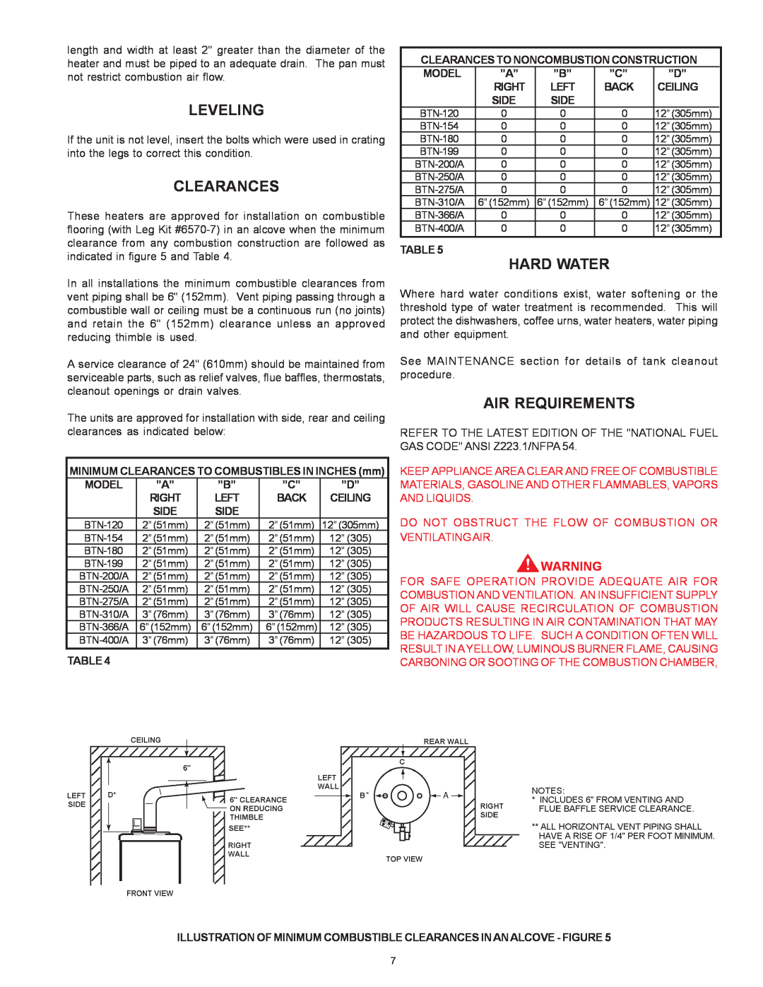
AIR REQUIREMENTS
LEVELING
CLEARANCES
HARD WATER
CONFINED SPACE
VENTING
MULTIPLE HEATER MANIFOLD
UNCONFINED SPACE
TYPE B GAS VENT Multiple Gas Fired Tank-Type Heaters
TABLE 6. TECHNICAL DATA VENTING
TABLE 6. TECHNICAL DATA VENTING Continued
RELIEF VALVE
WATER LINE CONNECTIONS
WATER POTABLE HEATING AND SPACE HEATING See pages
THERMOMETERS Not Supplied
DANGER
INSTALLATION DIAGRAMS-TOP INLET/OUTLET USAGE
GENERAL
CODE RESTRICTIONS
TEMPERATURE AT FIXTURES. SEE WATER TEMPERATURE CONTROL
VERTICAL STORAGE TANK AND FORCED CIRCULATION
HORIZONTAL STORAGE TANK AND FORCED CIRCULATION
TEMPERATURE SETTING SHOULD NOT EXCEED SAFE USE
WITH RECIRCULATION OF SANITIZING LOOP
TWO TEMPERATURE - ONE HEATER HIGH TEMPERATURE STORAGE
TWO TEMPERATURE - TWO HEATERS, ONE PRE-HEATER/ONE - BOOSTER HEATER
INSTALLATION DIAGRAMS-SIDE INLET/OUTLET USAGE
WITH OR WITHOUT BUILDING RECIRCULATION
HEATER WITH MIXING VALVE AND RECIRCULATED SANITIZING LOOP
ONE OR TWO TEMPERATURE - ONE HEATERS,HIGH TEMPERATURE
STORAGE WITH OR WITHOUT RECIRCULATION
HEATER WITH OR WITHOUT MIXING VALVE
TWO PRE-HEATERS WITH BOOSTER HEATER
TWO TEMPERATURE - TWO PRE-HEATERS WITH MIXING VALVE OR BOOSTER
HEATER WITH OR WITHOUT BUILING RECIRCULATION
TWO PRE-HEATERS WITH MIXING VALVE
HORIZONTAL STORAGE TANK
MEDIUM TEMPERATURE - ONE HEATER WITH AUXILIARY STORAGE TANK FORCED
CIRCULATION WITH OR WITHOUT BUILDING RECIRCULATION
VERTICAL STORAGE TANK
FOUR UNIT MANIFOLD KIT
MANIFOLD KITS
TWO UNIT MANIFOLD KIT
THREE UNIT MANIFOLD KIT
FIGURE 9 - SINGLE UNIT WIRING DIAGRAM BTN-120 THROUGH 400A
HEATER WIRING
CUBIC FEET PER HOUR
GAS PIPING
GAS PRESSURE REGULATOR
TABLE 7 - GAS SUPPLY LINE SIZES IN INCHES MAXIMUM CAPACITY OF PIPE IN
1 CU. FT. OF GAS AT FULL CAPACITY
OPERATION
MANIFOLD GAS PRESSURE IN INCHES OF WATER COLUMN ALL MODELS
APPROXIMATE TIME REQUIRED TO CONSUME
SEQUENCE OF OPERATION
LIGHTING AND OPERATION INSTRUCTIONS
FOR YOUR SAFETY READ BEFORE OPERATING
OPERATING INSTRUCTIONS
WATER TEMPERATURE CONTROL
PREVENTIVE MAINTENANCE
CHECK THE IGNITOR ASSEMBLY
IGNITOR ASSEMBLY
FIGURE 11, IGNITOR
MAIN BURNER
GAS VALVES
CHECKING THE INPUT
ANODE ROD INSPECTION
VENTING SYSTEM
REMOTE STORAGE TANK TEMPERATURE CONTROL
HOT WATER ODOR
DELIMING USING FLO-JUG METHOD
RECOMMENDED PROCEDURE FOR
TANK CLEANOUT PROCEDURE
DELIMING SOLVENTS
ELECTRICAL SERVICING
SERVICE
SYSTEM DIAGNOSTICS
IGNITION MODULE SYSTEM
SEQUENCE OF OPERATION FLOW CHART
REPLACEMENT PARTS, SERVICE HANDBOOKS AND TRAINING AIDS
REPLACEMENT PARTS
COMPLAINT
OPERATIONAL CHECKLIST
SERVICEMAN
REMEDY
KEEPTHISWARRANTYPOSTEDADJACENTTOTHEHEATERFORFUTUREREFERENCE
Model BTN Limited Warranty
4. SERVICEANDREPAIREXPENSES
6. CLAIMPROCEDURE
Top
Page
Image
Contents