Note: If your container does not have the vent cap and vent boss, drill a 3/16" hole in the handle. When you have finished deliming you will be able to plug this drilled vent with the stainless steel screw that is supplied with the kit.
2.Remove the container's cap and cut the plastic membrane located in the 3/4" IPT opening in the cap. Take care to not damage the threads.
3.Find the 3/4" male adapter, apply teflon tape to the threaded end and screw it into the 3/4" IPT opening in the cap.
4.Put cap with male adapter back on the container and slide 3/4" hose over end of male adapter and fasten in place using hose clamp provided.
Delime using
5.Slide the hose clamp over end of hose and slide hose over the male adapter in the water heater drain opening and secure in place using hose clamp.
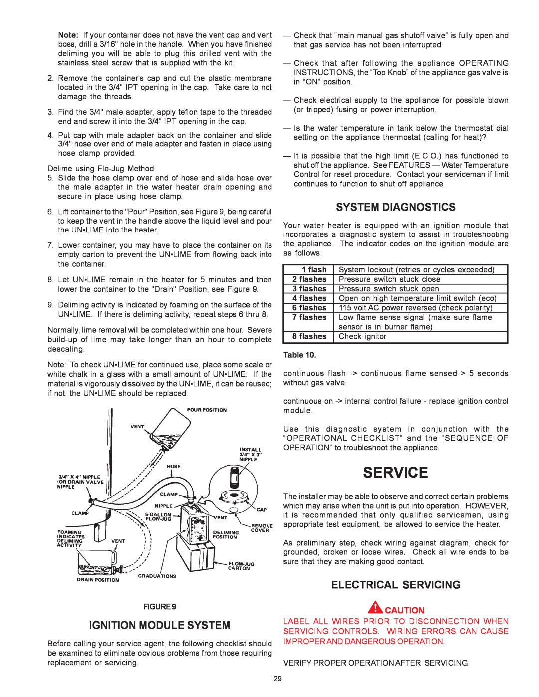
6.Lift container to the "Pour" Position, see Figure 9, being careful to keep the vent in the handle above the liquid level and pour the UN•LIME into the heater.
7.Lower container, you may have to place the container on its empty carton to prevent the UN•LIME from flowing back into the container.
8.Let UN•LIME remain in the heater for 5 minutes and then lower the container to the "Drain" Position, see Figure 9.
9.Deliming activity is indicated by foaming on the surface of the UN•LIME. If there is deliming activity, repeat steps 6 thru 8.
Normally, lime removal will be completed within one hour. Severe
Note: To check UN•LIME for continued use, place some scale or white chalk in a glass with a small amount of UN•LIME. If the material is vigorously dissolved by the UN•LIME, it can be reused; if not, the UN•LIME should be replaced.
FIGURE9
IGNITION MODULE SYSTEM
Before calling your service agent, the following checklist should be examined to eliminate obvious problems from those requiring replacement or servicing.
—Check that “main manual gas shutoff valve” is fully open and that gas service has not been interrupted.
—Check that after following the appliance OPERATING INSTRUCTIONS, the “Top Knob” of the appliance gas valve is in “ON” position.
—Check electrical supply to the appliance for possible blown (or tripped) fusing or power interruption.
—Is the water temperature in tank below the thermostat dial setting on the appliance thermostat (calling for heat)?
—It is possible that the high limit (E.C.O.) has functioned to shut off the appliance. See FEATURES — Water Temperature Control for reset procedure. Contact your serviceman if limit continues to function to shut off appliance.
SYSTEM DIAGNOSTICS
Your water heater is equipped with an ignition module that incorporates a diagnostic system to assist in troubleshooting the appliance. The indicator codes on the ignition module are as follows:
1 flash | System lockout (retries or cycles exceeded) | |
2 flashes | Pressure switch stuck close | |
3 flashes | Pressure switch stuck open |
|
4 flashes | Open on high temperature limit switch (eco) | |
6 flashes | 115 volt AC power reversed (check polarity) | |
7 flashes | Low flame sense signal (make sure flame | |
| sensor is in burner flame) | |
8 flashes | Check ignitor | |
Table 10. |
|
|
continuous flash
continuous on
Use this diagnostic system in conjunction with the “OPERATIONAL CHECKLIST” and the “SEQUENCE OF OPERATION” to troubleshoot the appliance.
SERVICE
The installer may be able to observe and correct certain problems which may arise when the unit is put into operation. HOWEVER, it is recommended that only qualified servicemen, using appropriate test equipment, be allowed to service the heater.
As preliminary step, check wiring against diagram, check for grounded, broken or loose wires. Check all wire ends to be sure that they are making good contact.
ELECTRICAL SERVICING
![]() CAUTION
CAUTION
LABEL ALL WIRES PRIOR TO DISCONNECTION WHEN SERVICING CONTROLS. WIRING ERRORS CAN CAUSE IMPROPER AND DANGEROUS OPERATION.
VERIFY PROPER OPERATION AFTER SERVICING.
29