Stored values are recalled from memory.

Configuration dipswitches are read.

Pending faults are recalled

Micros on all boards start running (indicated by a flashing Yellow LED near each micro)

Input sensors are read

Communications between micros and boards is established

FCB's are configurated with the number of ignition trials to run.

3.After initialization is complete (approximately 10 seconds) the system turns the green LED off and goes to the standby mode (yellow "Standby" LED on), unless a previously stored fault has been recalled, which will send the system into the service model (red "Service" LED on). In standby mode the display shows the temperature screen and in fault mode the current error screen is displayed.

4.The system then compares the temperature read from the controlling probe (inlet or tank) to the setpoint temperature. If the temperature is less than the operating setpoint minus the differential temperature and the thermostat input is closed then a call for heat is established and the system shifts to the run mode (green "Running" LED turns on).

5.The heating sequence begins by applying power to the pump and, if selected, the powered vent and the IRI gas valve.

6.After a few seconds the High Speed Blower (on all stages with the blower dipswitch turned on) are turned on to perform a cold purge of the chamber.

7.After cold purging is complete the blowers are turned off and the stage 1 blower is turned on.

8.The stage 1 igniter is turned on.

9.After 18 seconds the system checks that the igniter has turned on. If this is ok then the system turns on the gas valve.

10.After 1.5 seconds the system checks the status of the flame sensor. Note: If the "Ignition Tries" dipswitch is set for 3 tries the system will not declare an error until it tries the ignition sequence three times. If it is set to 1 try then the system will declare an error anytime a fault is detected.

11.The system now activates the other FCB stages depending upon a control algorithm scheme that is described below. For this example it is assumed that all four stages of heat are required.

12.The stage 2 blower is turned on to purge the chamber.

13.After approximately 10 seconds the stage 2 igniter is turned on.

14.After 18 seconds the system checks that the igniter has turned on. If this is ok then the system turns on the gas valve.

15.After 1.5 seconds the system checks the status of the flame sensor.

16.Steps 12 through 15 are then repeated for stage 3 and 4.

17.The system is now in the heating mode with all four stages on and will remain in this mode until the call for heat is satisfied or a fault occurs.

NOTE: In standby and running modes the system constantly monitors the signals and the internal operation for faults. Any detected fault will halt the heating sequence and shift the system to the service mode, where the detected fault will be displayed.

Temperature Setpoints (System Control Algorithm)

The boiler has a hysteresis type control, which means that it will begin heating the water when the temperature sensed by the

control probe (inlet or tank) falls below the operating setpoint minus the differential setpoint for stage 1. It will stop heating the water when the temperature rises to the operating setpoint. If the system has multiple stages then the differential setpoint for each stage is also subtracted from the operating setpoint. The following examples will further explain this operation.

Setup: 2 stage system, operating setpoint - 140, stage 1 to 2 differential setpoints = 10.

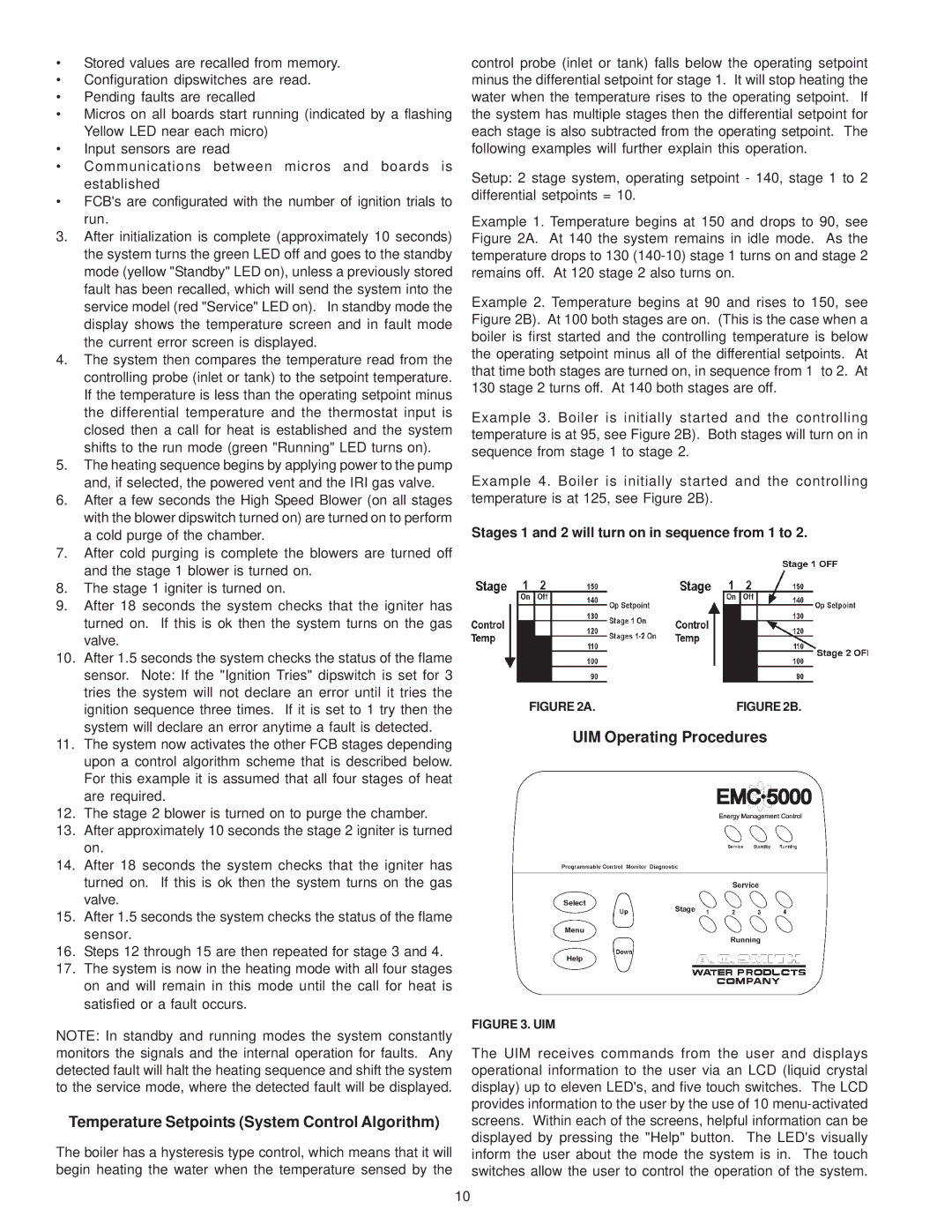
Example 1. Temperature begins at 150 and drops to 90, see Figure 2A. At 140 the system remains in idle mode. As the temperature drops to 130 (140-10) stage 1 turns on and stage 2 remains off. At 120 stage 2 also turns on.

Example 2. Temperature begins at 90 and rises to 150, see Figure 2B). At 100 both stages are on. (This is the case when a boiler is first started and the controlling temperature is below the operating setpoint minus all of the differential setpoints. At that time both stages are turned on, in sequence from 1 to 2. At 130 stage 2 turns off. At 140 both stages are off.

Example 3. Boiler is initially started and the controlling temperature is at 95, see Figure 2B). Both stages will turn on in sequence from stage 1 to stage 2.

Example 4. Boiler is initially started and the controlling temperature is at 125, see Figure 2B).

Stages 1 and 2 will turn on in sequence from 1 to 2.

FIGURE 2A.

FIGURE 2B.

UIM Operating Procedures

FIGURE 3. UIM

The UIM receives commands from the user and displays operational information to the user via an LCD (liquid crystal display) up to eleven LED's, and five touch switches. The LCD provides information to the user by the use of 10 menu-activated screens. Within each of the screens, helpful information can be displayed by pressing the "Help" button. The LED's visually inform the user about the mode the system is in. The touch switches allow the user to control the operation of the system.

10

Page 10
Image 10
A.O. Smith 750 SERIES, GB/GW-300, 500, 650 warranty Temperature Setpoints System Control Algorithm, UIM Operating Procedures

500, 750 SERIES, 650, GB/GW-300 specifications

The A.O. Smith GB/GW-300, 650, 750 Series, and 500 represent a cutting-edge line of commercial water heaters designed to meet the diverse needs of various applications. These models are highly regarded for their advanced features, robust construction, and reliable performance, making them ideal for businesses such as restaurants, hotels, and industrial facilities.

One of the main features of the A.O. Smith GB/GW series is its high-efficiency design. These water heaters are built with advanced insulation and heat exchanger technology, which contribute to reduced energy consumption and lower operating costs. The products achieve notable energy efficiency ratings, ensuring that businesses can maintain their hot water supply without incurring excessive utility bills.

The GB/GW series also incorporates a user-friendly digital control system. This technology allows operators to monitor and adjust settings easily, providing real-time feedback on temperature and energy consumption. This level of control enhances operational efficiency and ensures hot water is always available when needed.

Another significant characteristic of the A.O. Smith GB/GW series is its durable construction. The units are designed with high-quality materials that resist corrosion and wear, extending their operational lifespan. The stainless steel tanks and heat exchangers are engineered to withstand high temperatures and pressure, making them reliable even in demanding environments.

Moreover, safety features are paramount in the design of these water heaters. The series includes multiple safety mechanisms, such as high-temperature limit switches and pressure relief valves, ensuring the safe operation of the unit at all times. This not only protects the equipment but also guarantees the safety of personnel using hot water.

The GB/GW series ranges in capacity, accommodating different sizes of operations. From the compact and efficient 300 model to the larger 650 and 750 units, the series offers flexibility to suit various demands. The 500 model strikes a balance between capacity and efficiency, making it a popular choice for medium-sized establishments.

In summary, the A.O. Smith GB/GW-300, 650, 750 Series, and 500 are exemplary choices for commercial water heating solutions. Their combination of efficiency, advanced technology, durable design, and comprehensive safety features ensures that businesses have access to reliable hot water, ultimately supporting their operational needs and enhancing service delivery.