TELEPHONE SETUP
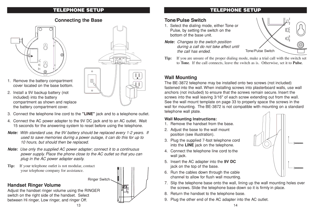
Connecting the Base
1. Remove the battery compartment cover located on the base bottom.
2. Install a 9V backup battery (not included) into the battery compartment as shown and replace the battery compartment cover.
3.Connect the telephone line cord to the "LINE" jack and to a telephone outlet.
4.Connect the AC power adapter to the 9V DC jack and to an AC outlet. Wait 15 seconds for the answering system to reset before using the telephone.
Note: With standard use, the 9V battery should be replaced every | ||||
used to save memories during a power outage, it can do this for up to | ||||
10 hours, but should then be replaced. |
|
|
| |
Note: Use only the supplied AC power adapter; connect it to a continuous | ||||
power supply. Place the phone close to the AC outlet so that you can | ||||
plug in the AC power adapter easily. |
|
|
| |
Tip: If your telephone outlet is not modular, contact |
|
|
| |
your telephone company for assistance. |
|
|
| |
|
|
|
|
|
| Ringer Switch |
|
|
|
Handset Ringer Volume |
| Ringer |
| Low Hi |
|
| |||
Adjust the handset ringer volume using the RINGER |
| |||
|
| Off | ||
switch on the right side of the handset. Select |
|
| ||
|
|
| ||
between Hi ringer, Low ringer, and ringer Off. |
|
|
| |
TELEPHONE SETUP
Tone/Pulse Switch
1. Select the dialing mode, either Tone or Pulse, by setting the switch on the bottom of the base unit.
Note: Changes to the switch position |
|
during a call do not take affect until | Tone/Pulse Switch |
the call has ended. |
Tip: If you are unsure of the proper dialing mode, make a trial call with the switch set to Tone. If the call connects, leave the switch as is. Otherwise, set it to Pulse.
Wall Mounting
The
Wall Mounting Instructions:
1.Remove the handset from the base.
2.Adjust the base to the wall mount position (see illustration).
3.Plug the supplied
into the LINE jack on the telephone.
4.Connect the telephone line cord to the wall jack.
5. Insert the AC adapter into the 9V DC jack on the top of the base.
6.Run the cables down through the cable channel to allow for flush wall mounting.
7.Slip the telephone base onto the wall, lining up the wall mounting holes over the screws. Slide the telephone base down so it is firmly in place.
8.Return the handset to the telephone base.
9.Plug the other end of the AC adapter into the AC outlet.
13 | 14 |