PAGE 7 | ASSEMBLY INSTRUCTION |
ASSEMBLY STAGE # 2
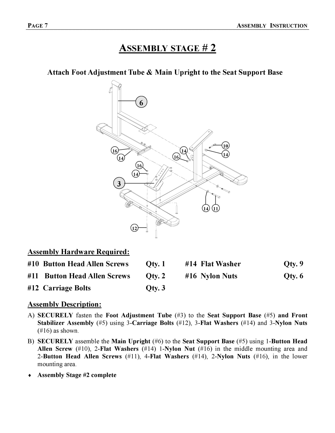
Attach Foot Adjustment Tube & Main Upright to the Seat Support Base
![]() 6
6![]()
![]()
16 |
| 14 | 10 | |
16 | 14 | |||
14 |
| |||
|
| |||
| 16 |
|
|
14
![]()
![]() 3
3![]()
![]()
14 | 11 |
12 |
|
Assembly Hardware Required: |
|
|
|
|
#10 Button Head Allen Screws | Qty. 1 | #14 | Flat Washer | Qty. 9 |
#11 Button Head Allen Screws | Qty. 2 | #16 | Nylon Nuts | Qty. 6 |
#12 Carriage Bolts | Qty. 3 |
|
|
|
Assembly Description:
A)SECURELY fasten the Foot Adjustment Tube (#3) to the Seat Support Base (#5) and Front Stabilizer Assembly (#5) using
B)SECURELY assemble the Main Upright (#6) to the Seat Support Base (#5) using
♦Assembly Stage #2 complete
