(English)
Description
3
1 | 6 |
| 2 | 4 |
| 7 | 5 | 8 |
|
|
|
|
| ||
|
|
|
|
|
| |
|
|
|
|
|
|
|
| Name |
|
| Description |
|
|
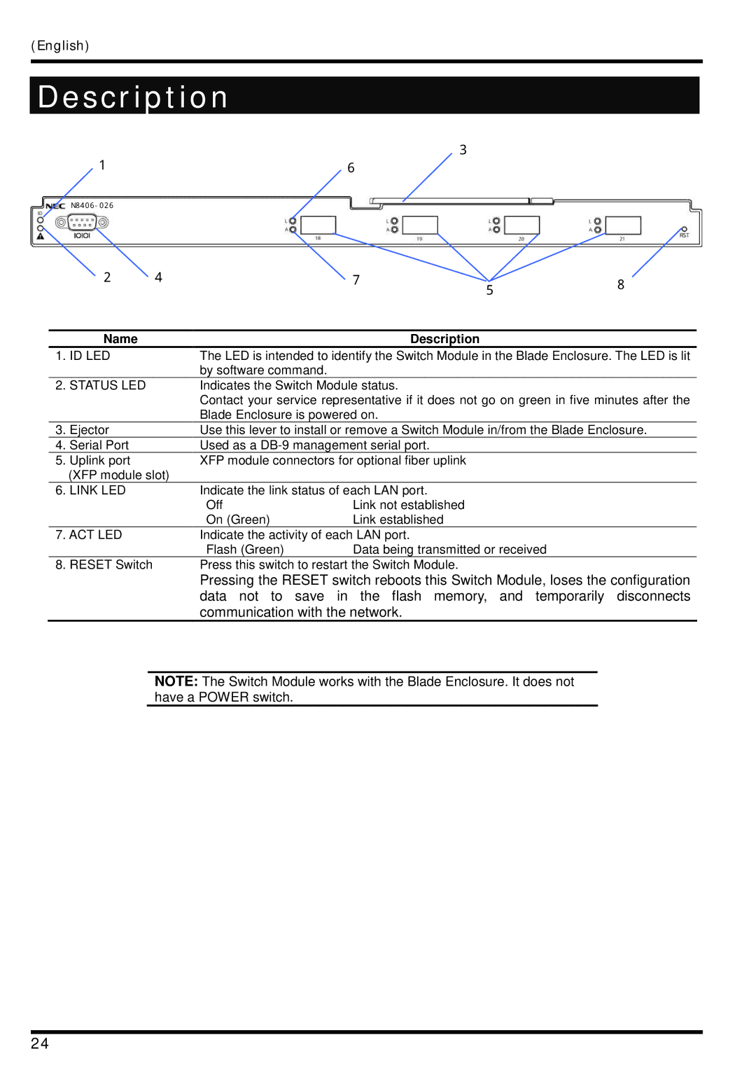
1. | ID LED |
| The LED is intended to identify the Switch Module in the Blade Enclosure. The LED is lit | |||
|
|
| by software command. |
|
|
|
2. | STATUS LED |
| Indicates the Switch Module status. |
|
| |
|
|
| Contact your service representative if it does not go on green in five minutes after the | |||
|
|
| Blade Enclosure is powered on. |
|
| |
3. | Ejector |
| Use this lever to install or remove a Switch Module in/from the Blade Enclosure. | |||
4. | Serial Port |
| Used as a |
|
| |
5. | Uplink port |
| XFP module connectors for optional fiber uplink |
|
| |
| (XFP module slot) |
|
|
|
| |
6. | LINK LED |
| Indicate the link status of each LAN port. |
|
| |
|
|
| Off | Link not established |
|
|
|
|
| On (Green) | Link established |
|
|
7. ACT LED |
| Indicate the activity of each LAN port. |
|
| ||
|
|
| Flash (Green) | Data being transmitted or received |
| |
8. | RESET Switch |
| Press this switch to restart the Switch Module. |
|
| |
Pressing the RESET switch reboots this Switch Module, loses the configuration data not to save in the flash memory, and temporarily disconnects communication with the network.
NOTE: The Switch Module works with the Blade Enclosure. It does not have a POWER switch.
24