使用上のご注意(Japanese)
お手入れ・内蔵機器の取り付けに関する注意事項
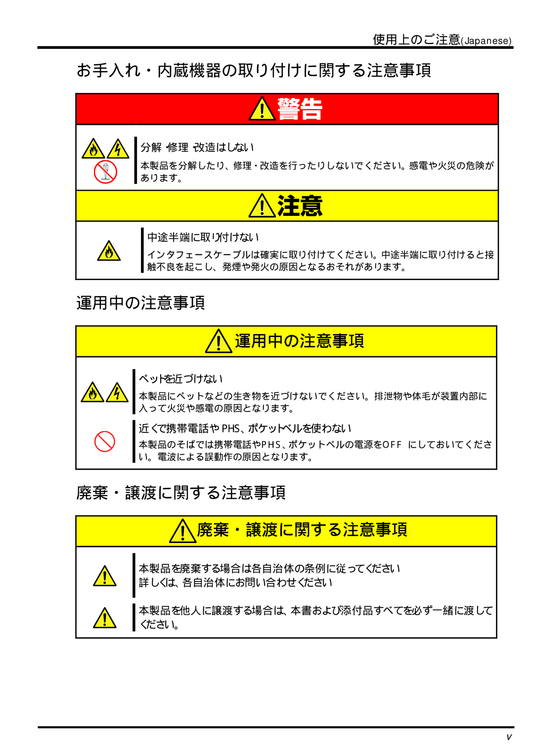
分解・修理・改造はしない
本製品を分解したり、修理・改造を行ったりしないでください。感電や火災の危険が あります。
中途半端に取り付けない
インタフェースケーブルは確実に取り付けてください。中途半端に取り付けると接 触不良を起こし、発煙や発火の原因となるおそれがあります。
運用中の注意事項
 運用中の注意事項
ペットを近づけない
本製品にペットなどの生き物を近づけないでください。排泄物や体毛が装置内部に 入って火災や感電の原因となります。
近くで携帯電話や PHS、ポケットベルを使わない
本製品のそばでは携帯電話やPHS、ポケットベルの電源をOFF にしておいてくださ い。電波による誤動作の原因となります。
廃棄・譲渡に関する注意事項
 廃棄・譲渡に関する注意事項
本製品を廃棄する場合は各自治体の条例に従ってください 詳しくは、各自治体にお問い合わせください
本製品を他人に譲渡する場合は、本書および添付品すべてを必ず一緒に渡して ください。
v