1.6.2 Front Panel Switches & Indicators Headers
This header is used for connecting switches and LED indicators on the chassis front panel.
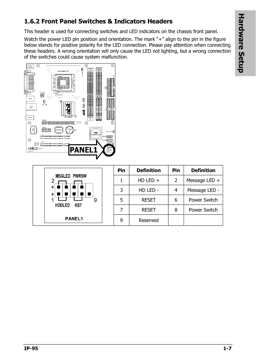
Watch the power LED pin position and orientation. The mark “+” align to the pin in the figure below stands for positive polarity for the LED connection. Please pay attention when connecting these headers. A wrong orientation will only cause the LED not lighting, but a wrong connection of the switches could cause system malfunction.
Hardware Setup
| Pin | Definition | Pin | Definition |
|
|
|
|
|
| 1 | HD LED + | 2 | Message LED + |
|
|
|
|
|
| 3 | HD LED - | 4 | Message LED - |
|
|
|
|
|
| 5 | RESET | 6 | Power Switch |
|
|
|
|
|
| 7 | RESET | 8 | Power Switch |
|
|
|
|
|
| 9 | Reserved |
|
|
|
|
|
|
|
|