Abit IP-95 manual Connecting Peripheral Devices, Floppy and IDE Disk Drive Connectors

Models: IP-95

1 40
Download 40 pages 57.45 Kb
Page 17
Image 17

1.8 Connecting Peripheral Devices

1.8.1 Floppy and IDE Disk Drive Connectors

Hardware Setup

The FDC1 connector connects up to two floppy drives with a 34-wire, 2-connector floppy cable. Connect the single end at the longer length of ribbon cable to the FDC1 on the board, the two connectors on the other end to the floppy disk drives connector. Generally you need only one floppy disk drive in your system.

The red line on the ribbon cable must be aligned with pin-1 on both the FDC1 port and the floppy connector.

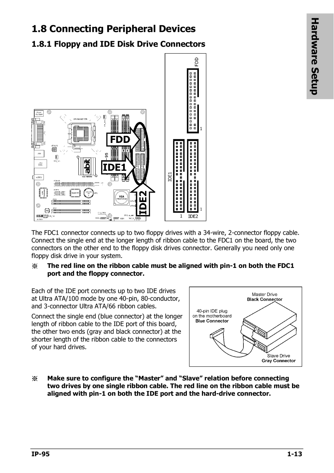
Each of the IDE port connects up to two IDE drives at Ultra ATA/100 mode by one 40-pin, 80-conductor, and 3-connector Ultra ATA/66 ribbon cables.

Connect the single end (blue connector) at the longer length of ribbon cable to the IDE port of this board, the other two ends (gray and black connector) at the shorter length of the ribbon cable to the connectors of your hard drives.

Make sure to configure the “Master” and “Slave” relation before connecting two drives by one single ribbon cable. The red line on the ribbon cable must be aligned with pin-1 on both the IDE port and the hard-drive connector.

IP-95

1-13

Page 17
Image 17
Abit IP-95 manual Connecting Peripheral Devices, Floppy and IDE Disk Drive Connectors