Main Unit Disassembly Process
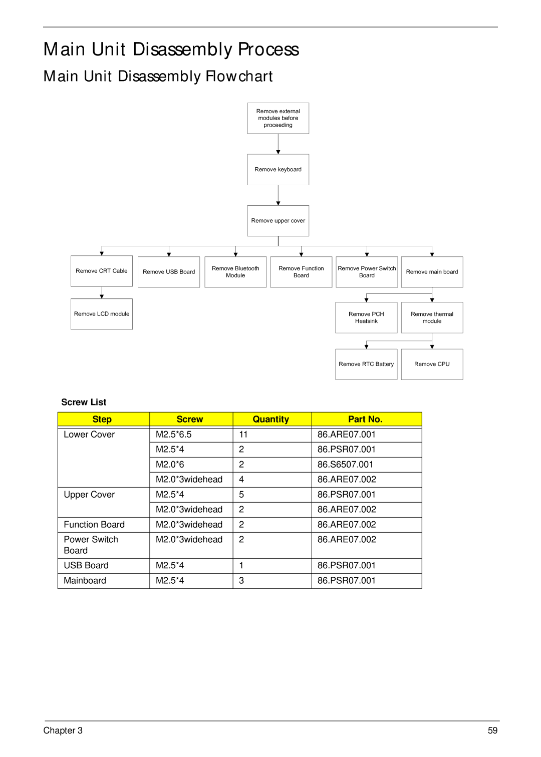
Main Unit Disassembly Flowchart
Remove external modules before proceeding
Remove keyboard
Remove upper cover
Remove CRT Cable
Remove USB Board
Remove Bluetooth
Module
Remove Function
Board
Remove Power Switch
Board
Remove main board
Remove LCD module
Remove PCH
Heatsink
Remove thermal
module
Remove RTC Battery
Remove CPU
Screw List
Step | Screw | Quantity | Part No. |
|
|
|
|
Lower Cover | M2.5*6.5 | 11 | 86.ARE07.001 |
|
|
|
|
| M2.5*4 | 2 | 86.PSR07.001 |
|
|
|
|
| M2.0*6 | 2 | 86.S6507.001 |
|
|
|
|
| M2.0*3widehead | 4 | 86.ARE07.002 |
|
|
|
|
Upper Cover | M2.5*4 | 5 | 86.PSR07.001 |
|
|
|
|
| M2.0*3widehead | 2 | 86.ARE07.002 |
|
|
|
|
Function Board | M2.0*3widehead | 2 | 86.ARE07.002 |
|
|
|
|
Power Switch | M2.0*3widehead | 2 | 86.ARE07.002 |
Board |
|
|
|
|
|
|
|
USB Board | M2.5*4 | 1 | 86.PSR07.001 |
|
|
|
|
Mainboard | M2.5*4 | 3 | 86.PSR07.001 |
|
|
|
|
Chapter 3 | 59 |