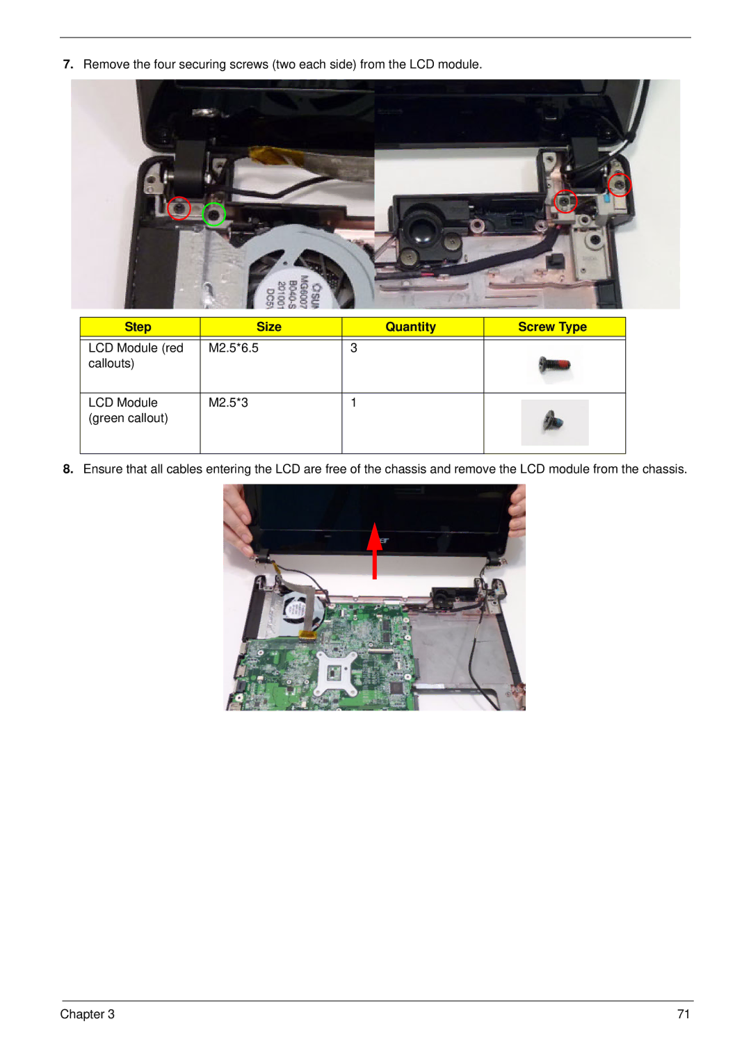
7.Remove the four securing screws (two each side) from the LCD module.
Step | Size | Quantity | Screw Type |
|
|
|
|
LCD Module (red | M2.5*6.5 | 3 |
|
callouts) |
|
|
|
|
|
|
|
LCD Module | M2.5*3 | 1 |
|
(green callout) |
|
|
|
|
|
|
|
8.Ensure that all cables entering the LCD are free of the chassis and remove the LCD module from the chassis.
Chapter 3 | 71 |
