Manuals
/
Acer
/
Computer Equipment
/
Laptop
Acer
4100, 4600
manual
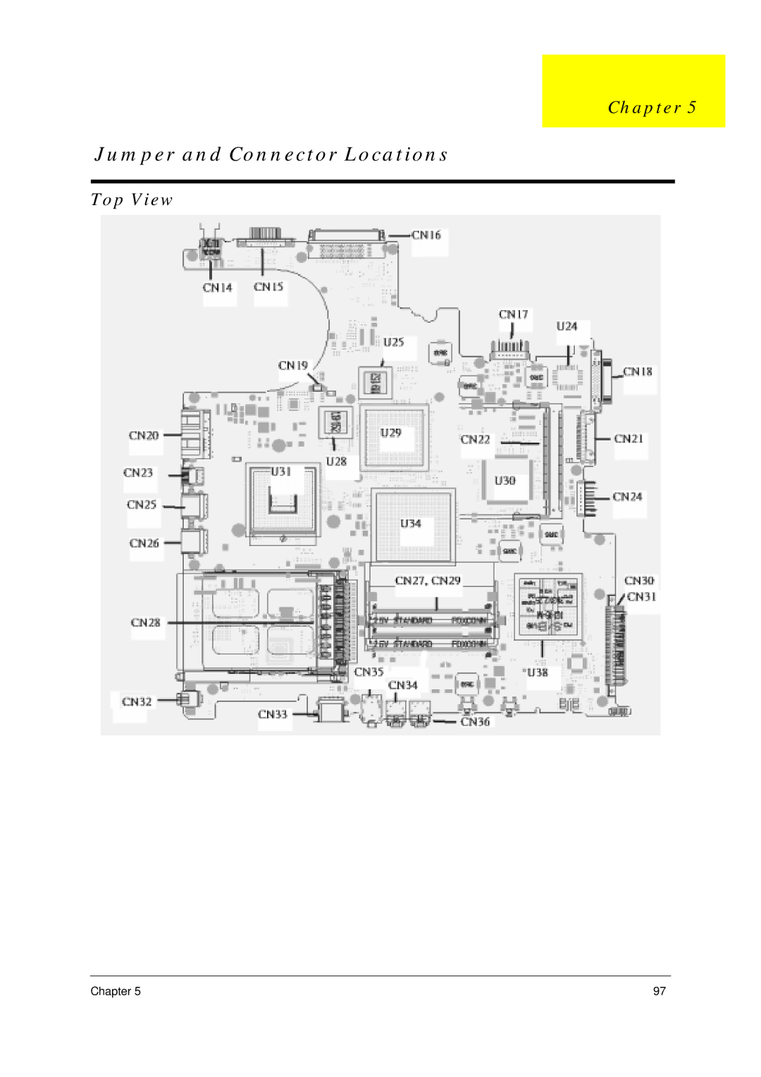
Jumper and Connector Locations, Top View
Models:
4100
4600
1
105
128
128
Download
128 pages
26.17 Kb
102
103
104
105
106
107
108
109
Troubleshooting
Specification
Dynamic Output Characteristics
Code list
Block Diagram
Password
Launch Key Default Application
Euro symbol
Indicators
Package configuration
Page 105
Image 105
Chapter 5
Jumper and Connector Locations
Top View
Chapter 5
97
Page 104
Page 106
Page 105
Image 105
Page 104
Page 106
Contents
TravelMate Aspire
Service Guide
Revision History
Disclaimer
Copyright
Messages
Conventions
Preface
Table of Contents
Chpater Jumper and Connector Locations
Chapter Troubleshooting
Chapter FRU Field Replaceable Unit List 101
Appendix C Online Support Information 120
Chapter
Features
Audio
Top View
Mainboard Placement
Rear View
Description
Crane
Block Diagram
Outlook View
TM 4600/ TM 4100 Open View
Description
AS 1690 Open View
TM 4600,TM 4100 and AS
Front Panel
TM 4600 / TM
Left View
TM 4600/ TM 4100/ AS
Right View
For TM4600 only
Bottom View
Description
Using the Keyboard
Lock keys
Lock Key Description
Desired action Num Lock on Num Lock off
Embedded Numeric Keypad
TM 4600 / TM
Indicators
When the battery is charging
Icon Description Power Lights when the computer is on
When in AC mode
Battery indicator
Windows Keys
Launch Keys
Launch Key Default Application
Key Description
Hot Key Function Description
Hot Keys
Using a computer security lock
Using System Utilities
Acer eManager
Icon Description
Launch Manager
Audio
Adjusting the Volume
Euro symbol
Special Keys
US dollar sign
Touchpad Basics
Touchpad
Function Left Button Righ Button Tap
Eject ing the optical CD or DVD drive tray
Hardware Specifications and Configurations
Specification
Controller
System Memory
USB Port
Package configuration
Battery
Mechanical Specifications
Optical Specification
Specifications
Output Ratings CC mode
Output Ratings CV mode
Dynamic Output Characteristics
Input Requirements
Details Model Aspire
Acpi Mode Power Management
360W x 273D x 27~32 Hmm
3lbs 2.86kg
Nominal Power Requirements
Logical Configuration
Physical & Environmental Specs Dimensions/Weight
Ambient Temperature
Vibration and Shock
Reliability Characteristics Error Rates
Seek time read, typical
Configuration
Environmental characteristics Operating
Physical size
Non-operating
Acoustics A-Weighted Sound Power Bels
Configuration/Orginzation
Seagate Specification
Performance
Reliability/Data Integrity
Storage
Specifications Details
DVD/CD RW Combo
DVD ROM
System Utilities
Bios Setup Utility
Parameter Description
Information
Main
Advanced Security Boot Exit
Parameter Description
Advanced
Description Option
Auto
Both
ECP
Parameter Description Option
Security
Set Supervisor/User Password
Disabled
Enter
Setup Notice Changes have been saved Continue
Exit
Boot
Exit
Info Main Advanced Security Boot
Chapter
General Information
Chapter
Disassembly Procedure Flowchart
Description
Screw List
Removing the Battery Pack
Removing the Memory and the Wireless LAN Card
Removing the Thermal Module and CPU
Removing the ODD Module
Removing the LCD Module
Disassembling the Main Unit
Disassembling the Upper Case Assembly
Disassembling the Lower Case Assembly
Chapter
Disassembling the LCD Module
Chapter
Disassembling the Optical Drive Module
Disassembling the External Modules
Chapter
Chapter
Troubleshooting
External Diskette Drive Check
System Check Procedures
External CD-ROM Drive Check
Keyboard or Auxiliary Input Device Check
Memory check
Power System Check
Check the Power Adapter
Touchpad Check
Check the Battery Pack
Power-On Self-Test Post Error Message
Index of Error Messages
Error Code List
Error Message List
CPU ID
No beep Error Messages FRU/Action in Sequence
Post Code
Code Beeps For Boot Block in Flash ROM
LCD-Related Symptoms
Index of Symptom-to-FRU Error Message
Indicator-Related Symptoms
Power-Related Symptoms
Memory-Related Symptoms
PCMCIA-Related Symptoms
Speaker-Related Symptoms
Power Management-Related Symptoms
Peripheral-Related Symptoms
Keyboard/Touchpad-Related Symptoms
Modem-Related Symptoms
Intermittent Problems
Dimm
Undetermined Problems
Use Napp CD to Build Master Hard Disc Drive
CD to Disk Recovery
Page
Chapter
Disk to Disk Recovery
Chapter
Page
Chapter
Top View
Jumper and Connector Locations
Rear View
Description
RTC Jumper
Chapter FRU Field Replaceable Unit List
Exploded Diagram
Chapter 103
Touch PAD Board ZL1A Touch PAD
Chapter 105
DVD/CDRW Combo ZL1 Combo QSI SBW
Chapter 107
108
Chapter 109
LCD Module 15 IN. Sxga ZL1 15 LCD SXGA+TM
Chapter 111
LCD Module 15.4 ZL1A 15.4 LCD Wxga TM
Chapter 113
LCD Screw Rubber PAD ZL1A Rubber PAD-UP
Appendix a Model Definition and Configuration
TravelMate 4100 series
Aspire 1690 series
Appendix B Test Compatible Components
Microsoft Windows XP Home Environment Test
Component Manufacturer Specifications
EBD11UD8ADDA
119
Appendix C Online Support Information
Top
Page
Image
Contents