3.See “Removing the PC and ExpressCard dummy cards” on page 56.
4.See “Removing the Lower Cover” on page 57.
5.See “Removing the DIMM” on page 58.
6.See “Removing the WLAN Board Modules” on page 59.
7.See “Removing the Hard Disk Drive Module” on page 61.
8.See “Removing the Optical Drive Module” on page 62.
9.See “Removing the Middle Cover” on page 66.
10.See “Removing the Keyboard” on page 69.
11.See “Removing the Heatsink Fan Module” on page 70.
12.See “Removing the CPU and VGA Heatsink Module” on page 71.
13.See “Removing the CPU” on page 72.
14.See “Removing the VGA Board (Discrete Model only)” on page 73.
15.See “Removing the LCD Module” on page 74.
16.See “Separating the Upper Case from the Lower Case” on page 76.
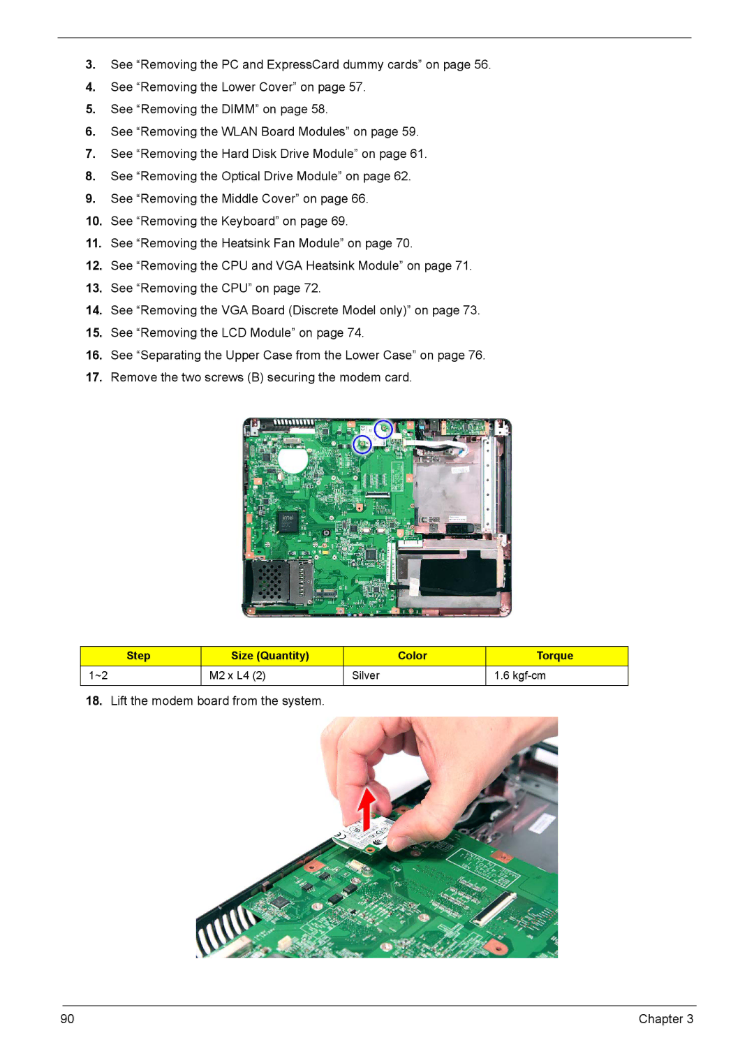
17.Remove the two screws (B) securing the modem card.
Step | Size (Quantity) | Color | Torque |
1~2 | M2 x L4 (2) | Silver | 1.6 |
|
|
|
|
18.Lift the modem board from the system.
90 | Chapter 3 |