External Module Disassembly Process
External Modules Disassembly Flowchart
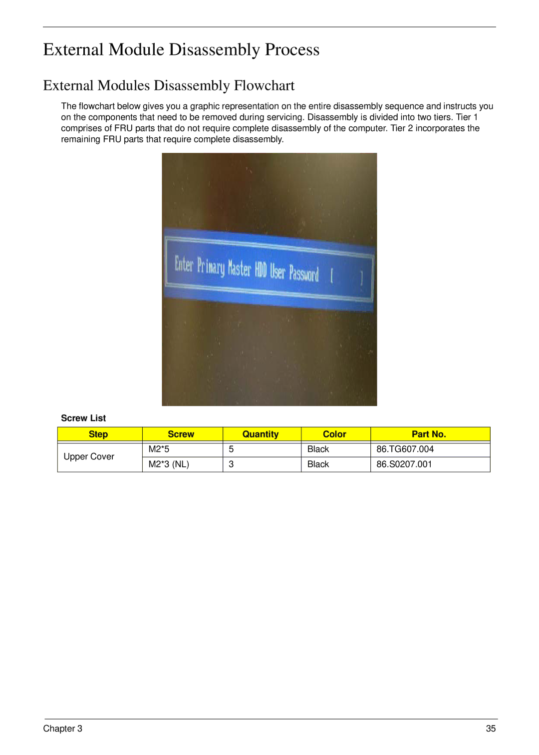
The flowchart below gives you a graphic representation on the entire disassembly sequence and instructs you on the components that need to be removed during servicing. Disassembly is divided into two tiers. Tier 1 comprises of FRU parts that do not require complete disassembly of the computer. Tier 2 incorporates the remaining FRU parts that require complete disassembly.
Screw List
Step | Screw | Quantity | Color | Part No. | |
|
|
|
|
| |
Upper Cover | M2*5 | 5 | Black | 86.TG607.004 | |
|
|
|
| ||
M2*3 (NL) | 3 | Black | 86.S0207.001 | ||
| |||||
|
|
|
|
|
Chapter 3 | 35 |
