Your Acoustic Research Subwoofer delivers powerful, deep bass sound output for a natural,
The
For simplicity, we call your Home Theater system’s or music system’s main speakers the Front speakers. We call your AV receiver, stereo receiver, or integrated amplifier the Receiver.
LOW PASS FREQUENCY CONTROL Adjusts the upper frequency limit for audio signals going to the Subwoofer amplifier. This control helps you adjust the systems tonal balance.
LEVEL CONTROL Balances the loudness of the Subwoofer relative to the Front speakers and compensates for room effects on the Subwoofer’s output.
PHASE SWITCH The Phase Switch controls the phase of the Subwoofer’s output relative to the front speakers. Listen carefully to the sound quality while playing a CD with low bass. Select the position of the switch that produces the fullest deep bass without boominess. You may need to readjust the Level and Low Pass Frequency controls after setting the Phase Switch.
SUBWOOFER ADJUSTMENT & USE
Subwoofer initial control settings
•Set the LOW PASS FREQUENCY Control to its center position.
•Set the LEVEL Control fully counterclockwise to MIN. You’ll reset this control after you make other adjustments.
Adjusting the Subwoofer controls
• | Play a program on your system. For the following adjustments, use |
| the Dolby ProLogic Normal surround mode and select a movie that |
| has a Dolby Surround soundtrack with a lot of music, or play a music |
| CD. Adjust the Receiver’s volume control for a comfortable sound |
| level from the system speakers. |
• | Increase the Subwoofer’s LEVEL Control setting clockwise, so that |
| you hear the deep bass. Adjust the control for a natural, musical |
program with plenty of bass, such as jazz or rock music, or an action movie.
•If everything else checks OK, take the Subwoofer to your dealer for service - THERE ARE NO USER SERVICEABLE PARTS INSIDE.
SPECIFICATIONS
Driver Complement and Enclosure
8” long throw woofer in a
Frequency Response 28Hz to 150Hz
Amplification
Power output: 150 Watts RMS, LFE In/Out
PLACEMENT | CONNECTING YOU SUBWOOFER |
balance that has plenty of deep bass sound when it is actually |
present in the music. |
Total Harmonic Distortion 10% @ 150 Watts output
Your AR subwoofer should be placed on the floor.You should be aware that the closer the subwoofer is placed to the wall,the more pronounced the bass will become,with maximum bass being achieved with the sub- woofer being placed in a corner.
To optimize you system's electronic components,try and keep all speaker wire and cables as short as possible.
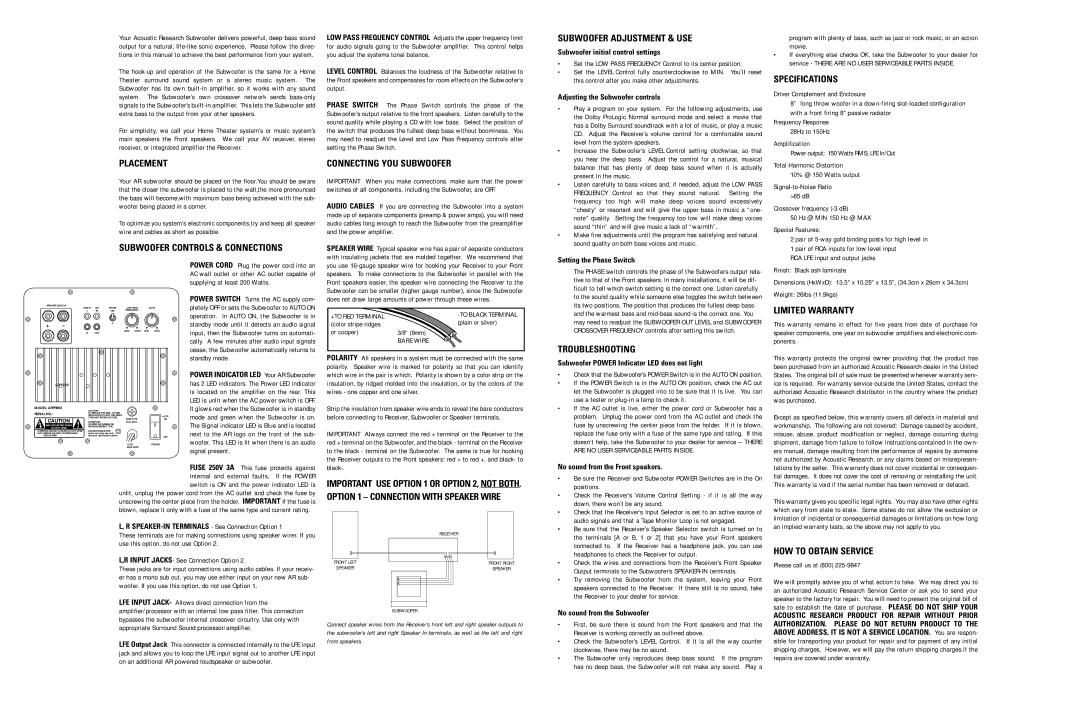
SUBWOOFER CONTROLS & CONNECTIONS
IMPORTANT When you make connections. make sure that the power switches of all components, including the Subwoofer, are OFF.
AUDIO CABLES If you are connecting the Subwoofer into a system made up of separate components (preamp & power amps), you will need audio cables long enough to reach the Subwoofer from the preamplifier and the power amplifier.
SPEAKER WIRE Typical speaker wire has a pair of separate conductors with insulating jackets that are molded together. We recommend that
• | Listen carefully to bass voices and, if needed, adjust the LOW PASS |
| FREQUENCY Control so that they sound natural. Setting the |
| frequency too high will make deep voices sound excessively |
| “chesty” or resonant and will give the upper bass in music a “one- |
| note” quality. Setting the frequency too low will make deep voices |
| sound “thin” and will give music a lack of “warmth”. |
• | Make fine adjustments until the program has satisfying and natural |
| sound quality on both bass voices and music. |
Setting the Phase Switch
Crossover frequency
50 Hz @ MIN 150 Hz @ MAX
Special Features:
2 pair of
RCA LFE input and output jacks
SPEAKER LEVEL IN
LINE IN | LFE | PHASE | LOW PASS | LEVEL |
L | IN | 180° | FREQUENCY |
|
POWER CORD Plug the power cord into an AC wall outlet or other AC outlet capable of supplying at least 200 Watts.
POWER SWITCH Turns the AC supply com- pletely OFF or sets the Subwoofer to AUTO ON operation. In AUTO ON, the Subwoofer is in
you use
+TO RED TERMINAL |
|
The PHASE switch controls the phase of the Subwoofers output rela- tive to that of the Front speakers. In many installations, it will be dif- ficult to tell which switch setting is the correct one. Listen carefully to the sound quality while someone else toggles the switch between its two positions. The position that produces the fullest deep bass and the warmest bass and
Finish: Black ash laminate
Dimensions (HxWxD): 13.5" x 10.25" x 13.5", (34.3cm x 26cm x 34.3cm)
Weight: 26lbs (11.9kgs)
LIMITED WARRANTY
+ –
0°
50HZ 150HZ MIN MAX
standby mode until it detects an audio signal
(color stripe ridges | (plain or silver) |
or cooper) |
|
R OUT
ARPR808 |
|
|
|
|
MODEL: ARPR808 |
| CAUTION: |
|
|
|
|
|
| |
SERIAL NO.: |
| TO REDUCE THE RISK OF FIRE, |
|
|
| REPLACE WITH ONLY THE SAME |
|
| |
CAUTION |
| TYPE AND RATING OF FUSE. | FUSE TYPE |
|
! |
|
| ||
ATTENTION: | T2AL 250V |
| ||
RISK OF ELECTRIC SHOCK | UTILISER UN FUSIBLE DE |
|
| |
DO NOT OPEN | RECHANGEMEME TYPE. |
|
| |
WARNING: SHOCK | DOUBLE INSULATION |
|
| |
AVIS: RISQUE DE CHOC | when servicing use only |
|
| |
PAS OUVRIR |
| identical replacement parts. |
|
|
|
|
| 115W | POWER |
|
|
| 60HZ 300W |
|
AUTO
ON
OFF
input, then the Subwoofer turns on automati- cally. A few minutes after audio input signals cease, the Subwoofer automatically returns to standby mode.
POWER INDICATOR LED Your AR Subwoofer has 2 LED indicators. The Power LED indicator is located on the amplifier on the rear. This LED is unlit when the AC power switch is OFF. It glows red when the Subwoofer is in standby mode and green when the Subwoofer is on. The Signal indicator LED is Blue and is located next to the AR logo on the front of the sub- woofer. This LED is lit when there is an audio signal present.
3/8” (9mm) |
BARE WIRE |
POLARITY All speakers in a system must be connected with the same polarity. Speaker wire is marked for polarity so that you can identify which wire in the pair is which. Polarity is shown by a color strip on the insulation, by ridged molded into the insulation, or by the colors of the wires - one copper and one silver.
Strip the insulation from speaker wire ends to reveal the bare conductors before connecting to Receiver, Subwoofer or Speaker terminals.
IMPORTANT Always connect the red + terminal on the Receiver to the red + terminal on the Subwoofer, and the black - terminal on the Receiver to the black - terminal on the Subwoofer. The same is true for hooking the Receiver outputs to the Front speakers: red + to red +, and black- to
FUSE 250V 3A This fuse protects against internal and external faults. If the POWER switch is ON and the power indicator LED is
unlit, unplug the power cord from the AC outlet and check the fuse by unscrewing the center piece from the holder. IMPORTANT If the fuse is blown, replace it only with a fuse of the same type and current rating.
IMPORTANT USE OPTION 1 OR OPTION 2, NOT BOTH. OPTION 1 – CONNECTION WITH SPEAKER WIRE
may need to readjust the SUBWOOFER OUT LEVEL and SUBWOOFER CROSSOVER FREQUENCY controls after setting this switch.
TROUBLESHOOTING
Subwoofer POWER Indicator LED does not light
•Check that the Subwoofer’s POWER Switch is in the AUTO ON position.
•If the POWER Switch is in the AUTO ON position, check the AC out let the Subwoofer is plugged into to be sure that it is live. You can use a tester or
•If the AC outlet is live, either the power cord or Subwoofer has a problem. Unplug the power cord from the AC outlet and check the fuse by unscrewing the center piece from the holder. If it is blown, replace the fuse only with a fuse of the same type and rating. If this doesn’t help, take the Subwoofer to your dealer for service – THERE ARE NO USER SERVICEABLE PARTS INSIDE.
No sound from the Front speakers.
• | Be sure the Receiver and Subwoofer POWER Switches are in the On |
| positions. |
• | Check the Receiver’s Volume Control Setting - if it is all the way |
| down, there won’t be any sound. |
• | Check that the Receiver’s Input Selector is set to an active source of |
| audio signals and that a Tape Monitor Loop is not engaged. |
This warranty remains in effect for five years from date of purchase for speaker components, one year on subwoofer amplifiers and electronic com- ponents.
This warranty protects the original owner providing that the product has been purchased from an authorized Acoustic Research dealer in the United States. The original bill of sale must be presented whenever warranty serv- ice is required. For warranty service outside the United States, contact the authorized Acoustic Research distributor in the country where the product was purchased.
Except as specified below, this warranty covers all defects in material and workmanship. The following are not covered: Damage caused by accident, misuse, abuse, product modification or neglect, damage occurring during shipment, damage from failure to follow instructions contained in the own- ers manual, damage resulting from the performance of repairs by someone not authorized by Acoustic Research, or any claims based on misrepresen- tations by the seller. This warranty does not cover incidental or consequen- tial damages. It does not cover the cost of removing or reinstalling the unit. This warranty is void if the serial number has been removed or defaced.
This warranty gives you specific legal rights. You may also have other rights which vary from state to state. Some states do not allow the exclusion or limitation of incidental or consequential damages or limitations on how long
L, R SPEAKER-IN TERMINALS - See Connection Option 1
These terminals are for making connections using speaker wirer. If you use this option, do not use Option 2.
L,R INPUT JACKS- See Connection Option 2
These jacks are for input connections using audio cables. If your receiv- er has a mono sub out, you may use either input on your new AR sub- woofer. If you use this option, do not use Option 1.
| RECEIVER |
FRONT LEFT | FRONT RIGHT |
SPEAKER | SPEAKER |
• | Be sure that the Receiver’s Speaker Selector switch is turned on to |
| the terminals [A or B, 1 or 2] that you have your Front speakers |
| connected to. If the Receiver has a headphone jack, you can use |
| headphones to check the Receiver for output. |
• | Check the wires and connections from the Receiver’s Front Speaker |
| Output terminals to the Subwoofer’s |
• | Try removing the Subwoofer from the system, leaving your Front |
| speakers connected to the Receiver. If there still is no sound, take |
| the Receiver to your dealer for service. |
an implied warranty lasts, so the above may not apply to you.
HOW TO OBTAIN SERVICE
Please call us at (800) 225-9847
We will promptly advise you of what action to take. We may direct you to an authorized Acoustic Research Service Center or ask you to send your speaker to the factory for repair. You will need to present the original bill of
LFE INPUT JACK- Allows direct connection from the amplifier/processor with an internal low pass filter. This connection bypasses the subwoofer internal crossover circuitry. Use only with appropriate Surround Sound processor/amplifier.
LFE Output Jack This connector is connected internally to the LFE input jack and allows you to loop the LFE input signal out to another LFE input on an additional AR powered loudspeaker or subwoofer.
SUBWOOFER
Connect speaker wires from the Receiver’s front left and right speaker outputs to the subwoofer’s left and right Speaker In terminals, as well as the left and right front speakers.
No sound from the Subwoofer
•First, be sure there is sound from the Front speakers and that the Receiver is working correctly as outlined above.
•Check the Subwoofer’s LEVEL Control. If it is all the way counter clockwise, there may be no sound.
•The Subwoofer only reproduces deep bass sound. If the program has no deep bass, the Subwoofer will not make any sound. Play a
sale to establish the date of purchase. PLEASE DO NOT SHIP YOUR
ACOUSTIC RESEARCH PRODUCT FOR REPAIR WITHOUT PRIOR AUTHORIZATION. PLEASE DO NOT RETURN PRODUCT TO THE ABOVE ADDRESS, IT IS NOT A SERVICE LOCATION. You are respon- sible for transporting your product for repair and for payment of any initial shipping charges. However, we will pay the return shipping charges if the repairs are covered under warranty.