|
|
|
|
|
|
|
|
|
|
|
|
|
|
|
|
|
|
|
|
|
|
|
|
|
|
|
|
|
|
|
|
|
|
|
|
|
|
|
|
|
|
|
|
|
|
|
|
|
|
|
|
|
|
|
|
| SENC 150 |
|
|
|
|
|
|
|
|
| Encoder Installation Procedure |
|
| |||||||||||
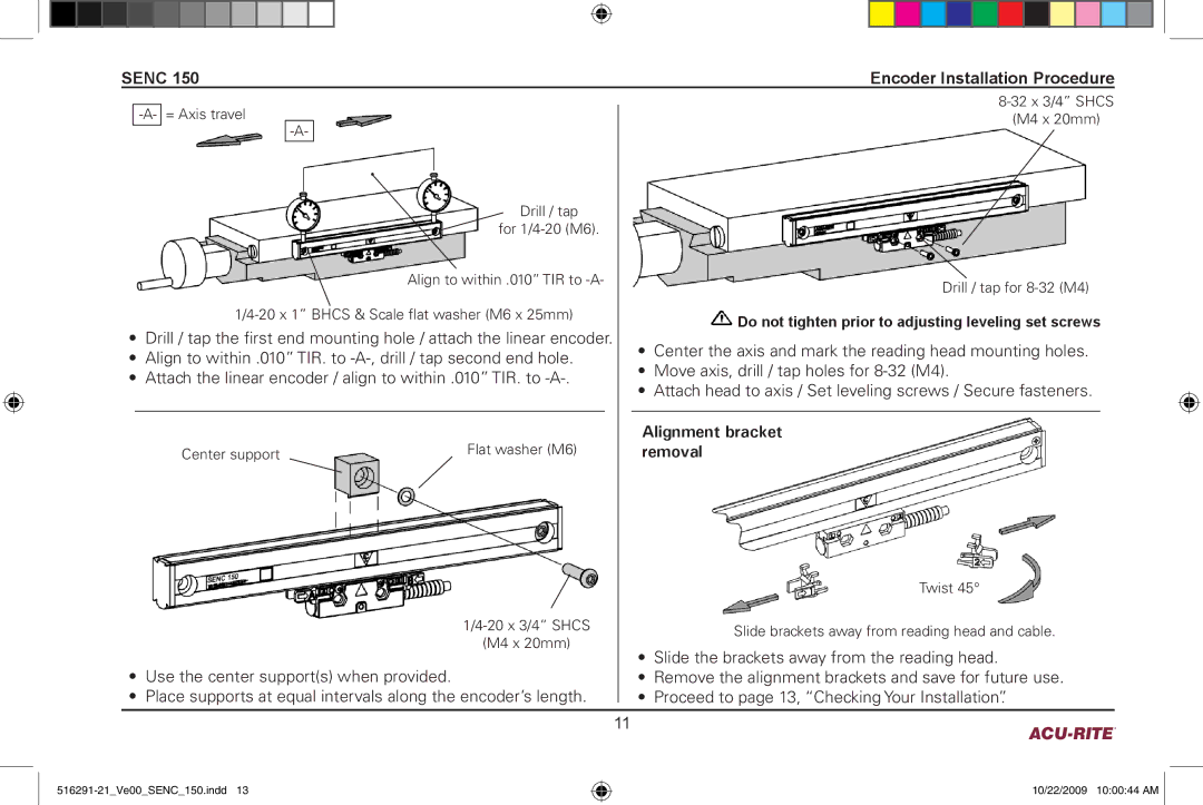
Drill / tap
for
Align to within .010” TIR to
•Drill / tap the first end mounting hole / attach the linear encoder.
•Align to within .010” TIR. to
•Attach the linear encoder / align to within .010” TIR. to
Center support | Flat washer (M6) |
|
(M4 x 20mm)
•Use the center support(s) when provided.
•Place supports at equal intervals along the encoder’s length.
(M4 x 20mm)
Drill / tap for
![]() Do not tighten prior to adjusting leveling set screws
Do not tighten prior to adjusting leveling set screws
•Center the axis and mark the reading head mounting holes.
•Move axis, drill / tap holes for
•Attach head to axis / Set leveling screws / Secure fasteners.
Alignment bracket removal
Twist 45°
Slide brackets away from reading head and cable.
•Slide the brackets away from the reading head.
•Remove the alignment brackets and save for future use.
•Proceed to page 13, “Checking Your Installation”.
|
|
|
11 |
| |
10/22/2009 10:00:44 AM ![]()