|
|
|
|
|
|
|
|
|
|
|
|
|
|
|
|
|
|
|
|
|
|
|
|
|
|
|
|
|
|
|
|
|
|
|
|
|
|
|
|
|
|
|
|
|
|
|
|
|
|
|
|
|
|
|
|
|
|
|
|
|
| Spar Installation Procedure |
|
|
|
|
|
|
|
|
| SENC 150 |
|
|
| ||||||||||||||
|
| These steps apply to all spar mounting conditions. |
|
|
|
|
|
|
|
|
|
|
|
|
|
|
| ||||||||||||
|
|
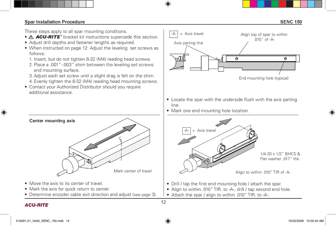
| = Axis travel | Align top of spar to within |
|
|
| ||||||||||||||||||||||
|
| • |
|
|
|
|
| ||||||||||||||||||||||
|
|
|
|
|
|
|
|
| |||||||||||||||||||||
|
|
|
|
|
|
| .015” of |
|
|
| |||||||||||||||||||
|
| • Adjust drill depths and fastener lengths as required. |
| Axis parting line |
|
|
|
|
| ||||||||||||||||||||
|
|
|
|
|
|
|
|
|
|
|
|
|
|
| |||||||||||||||
•When instructed on page 12: Adjust the leveling set screws as follows:
| 1. Insert, but do not tighten |
|
|
|
|
|
| |
| 2. Place |
|
|
|
|
|
| |
| and mounting surface. |
|
|
|
|
|
| |
| 3. Adjust each set screw until a slight drag is felt on the shim. |
|
|
|
| End mounting hole (typical) | ||
| 4. Evenly tighten the |
|
|
|
| |||
|
|
|
|
|
|
| ||
• Contact your Authorized Distributor should you require |
|
|
|
|
|
| ||
| additional assistance. |
|
|
|
|
|
| |
|
|
| • Locate the spar with the underside flush with the axis parting | |||||
|
|
|
|
| line. | |||
|
|
| • Mark one end mounting hole location. | |||||
|
|
|
|
|
|
|
|
|
| Center mounting axis |
|
|
|
|
|
| |
|
|
|
|
|
|
|
| |
|
|
|
|
|
| = Axis travel | ||
| C |
|
|
|
|
|
| |
|
|
|
|
|
|
| ||
| L |
|
|
|
| |||
|
|
|
|
|
|
| ||
|
|
|
|
|
|
| ||
|
|
|
|
|
|
| ||
|
|
|
|
|
|
| ||
|
|
|
|
|
|
| Flat washer .017” thk. | |
| Mark center of travel |
|
|
|
| Align to within .010” TIR of | ||
• | Move the axis to its center of travel. | • | Drill / tap the first end mounting hole / attach the spar. | |||||
• | Mark the axis for quick return to center. | • | Align to within .010” TIR. to | |||||
• Determine encoder cable exit direction and adjust (see page 3). | • Attach the spar / align to within .010” TIR. to | |||||||
| 12 |
|
|
|
|
| ||
10/22/2009 10:00:44 AM ![]()