MAN-FC2002-001 specifications
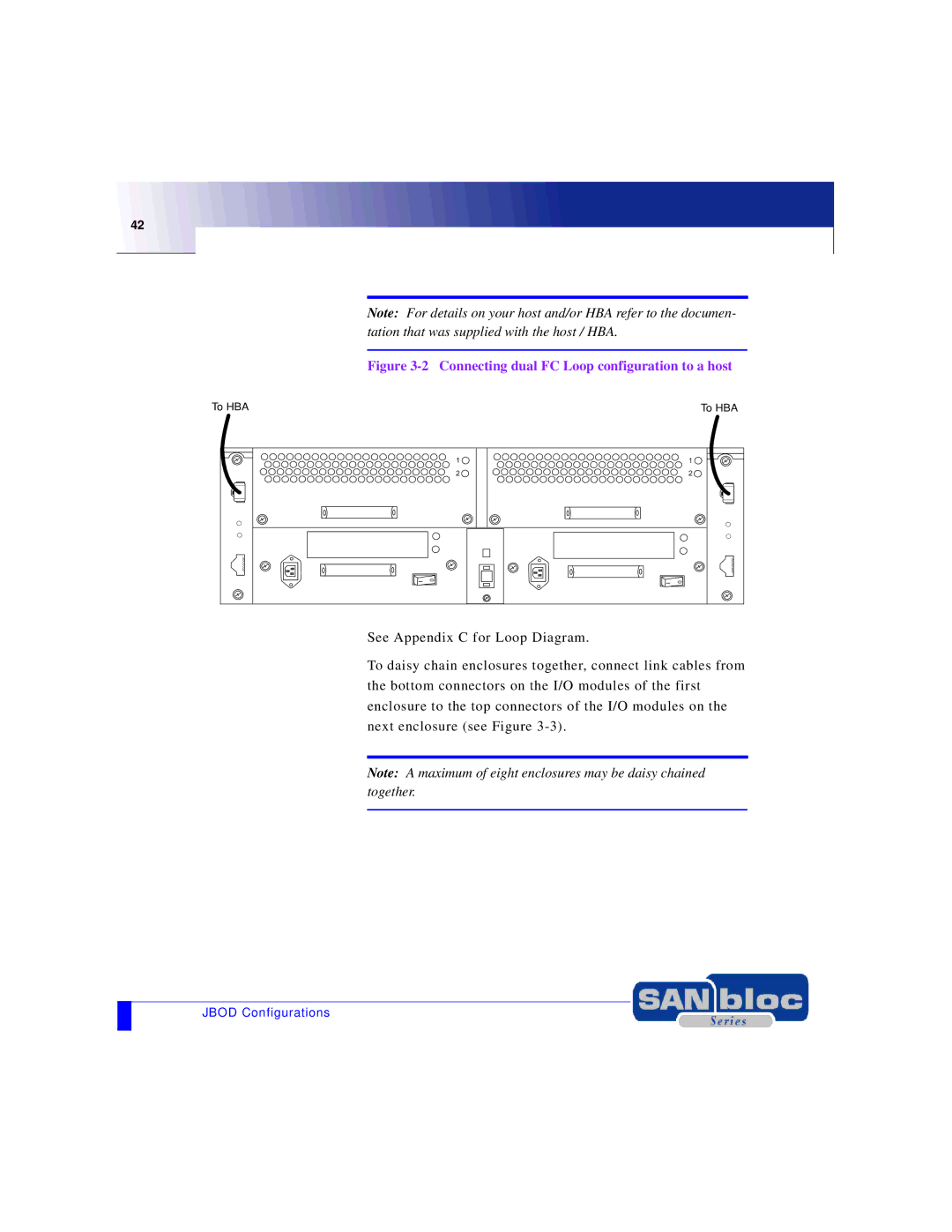
The Adaptec MAN-FC2002-001 is a high-performance storage controller designed to address the needs of enterprise-level data management. This Fibre Channel host bus adapter (HBA) is engineered to facilitate fast and reliable data transfer between servers and storage devices, thereby enhancing overall storage performance. One of its standout features is the support for 2 Gbps Fibre Channel technology, which enables rapid communication in environments where speed is critical.This controller is equipped with dual-channel architecture that provides advanced connectivity options. This design not only improves bandwidth utilization but also allows for simultaneous access to multiple storage devices, enhancing system efficiency. With its robust architecture, the MAN-FC2002-001 supports both point-to-point and switched fabric connectivity, giving users flexibility in their configurations based on their unique storage environment.
One of the key technologies incorporated in the Adaptec MAN-FC2002-001 is its advanced error checking and correction capabilities. These features help protect data integrity during transmission, minimizing data loss risks. Additionally, the HBA supports an array of operating systems, including various UNIX distributions and Windows servers, making it a versatile choice for diverse IT infrastructures.
Performance-wise, the controller is optimized for high I/O operations, making it suitable for demanding applications such as databases, virtualization, and large file transfers. With support for advanced queuing techniques, it can efficiently manage a high volume of data requests, thus reducing latency and enhancing response times.
In terms of compatibility, the Adaptec MAN-FC2002-001 easily integrates with external storage arrays, providing users with options to scale their storage solutions as needed. The card is designed for both backward compatibility with older Fibre Channel infrastructures and forward compatibility with the latest technologies, thereby extending the investment value for enterprises.
To complement its technical capabilities, the MAN-FC2002-001 features a comprehensive set of management tools, allowing system administrators to monitor performance metrics, manage firmware updates, and configure settings easily. Its reliable design and robust performance characteristics make the Adaptec MAN-FC2002-001 an ideal choice for organizations looking to enhance their storage network infrastructure while maintaining high availability and reliability. Overall, the Adaptec MAN-FC2002-001 represents a powerful solution for modern data storage challenges.

