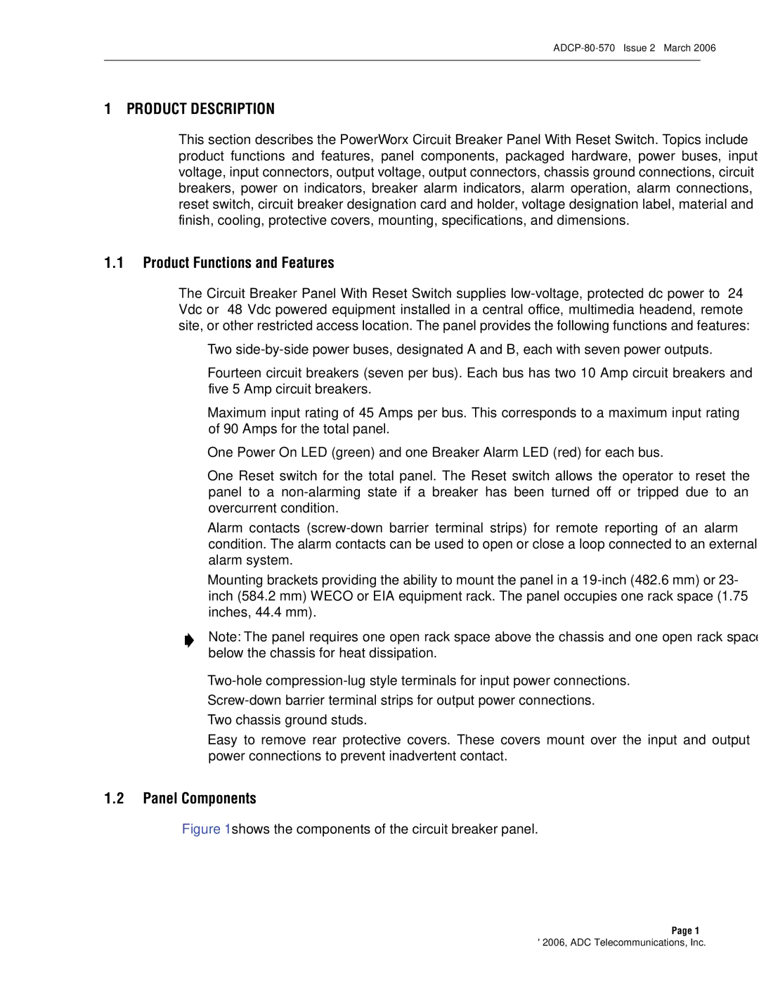
Circuit Breaker Panel With Reset Switch specifications
An ADC Circuit Breaker Panel with Reset Switch is an essential component in modern electrical systems, designed to enhance safety and efficiency in power distribution. This panel serves as a protective mechanism, safeguarding electrical circuits from overloads and short circuits, while the reset switch provides a user-friendly means of restoring functionality without the need for complete disconnection.One of the primary features of the ADC Circuit Breaker Panel is its advanced circuit protection technology. Utilizing either thermal or magnetic mechanisms, these breakers can detect abnormalities in current flow and automatically interrupt the circuit. Thermal breakers respond to excessive heat generated by an overload, while magnetic breakers react quickly to short circuits, ensuring minimal damage to both the electrical system and connected appliances.
Another important characteristic of this panel is its modular design. The customizable layout allows for the integration of various circuit breakers based on specific requirements, accommodating different circuit voltages and capacities. This adaptability makes the ADC Circuit Breaker Panel suitable for a wide range of applications, from residential homes to commercial buildings and industrial settings.
Energy efficiency is a key concern in modern electrical design, and the ADC panel plays a significant role in this aspect. With features like smart monitoring systems, users can keep track of power consumption, helping to identify inefficiencies and reduce energy waste. This promotes sustainable practices and can lead to significant cost savings over time.
Incorporating modern technologies, these panels often come equipped with digital displays and connectivity options. This enables real-time monitoring and alerts for any irregularities, enhancing overall system reliability. Some models even support remote access, allowing users to manage and monitor their electrical systems from anywhere, further increasing convenience and safety.
Moreover, safety is paramount in the design of ADC Circuit Breaker Panels. The inclusion of a reset switch means that instead of replacing blown fuses or constantly resetting breakers manually, users can simply press the switch to restore power. This feature not only saves time but also reduces the risk of accidental electrical mishaps.
In summary, the ADC Circuit Breaker Panel with Reset Switch blends advanced technology, adaptability, and enhanced safety features into a compact design. With its capacity for efficient energy management and user-friendly operation, it stands out as a crucial element in the evolution of electrical distribution and protection systems.

