Installation | |
|
|
Use a null modem connector for
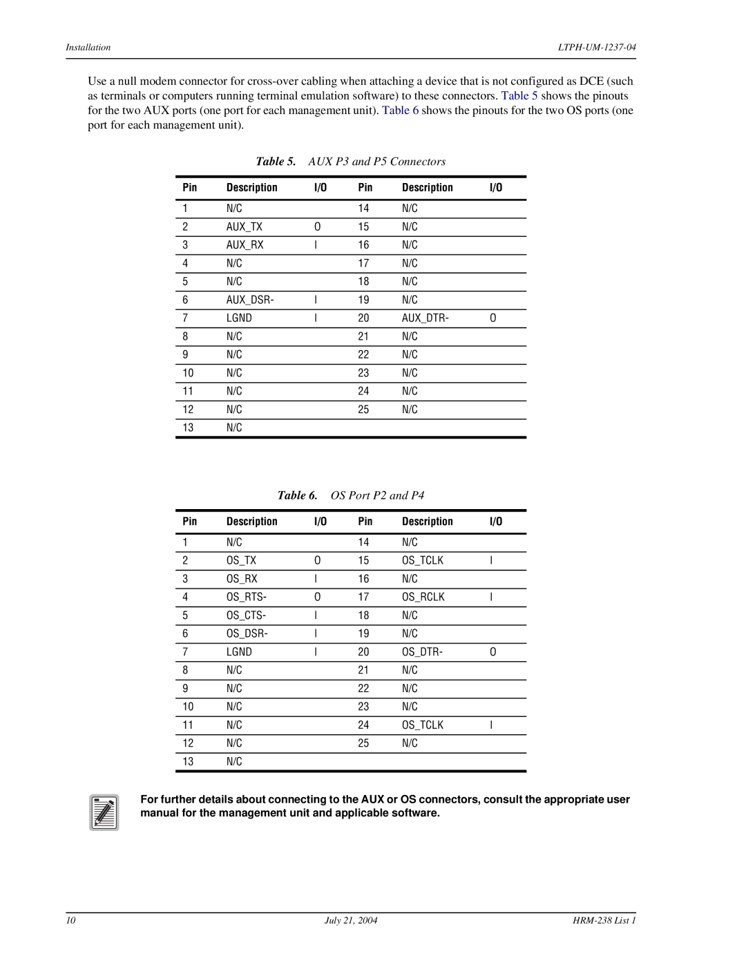
Table 5. AUX P3 and P5 Connectors
Pin | Description | I/O | Pin | Description | I/O |
|
|
|
|
|
|
1 | N/C |
| 14 | N/C |
|
|
|
|
|
|
|
2 | AUX_TX | O | 15 | N/C |
|
|
|
|
|
|
|
3 | AUX_RX | I | 16 | N/C |
|
|
|
|
|
|
|
4 | N/C |
| 17 | N/C |
|
|
|
|
|
|
|
5 | N/C |
| 18 | N/C |
|
|
|
|
|
|
|
6 | AUX_DSR- | I | 19 | N/C |
|
|
|
|
|
|
|
7 | LGND | I | 20 | AUX_DTR- | O |
|
|
|
|
|
|
8 | N/C |
| 21 | N/C |
|
|
|
|
|
|
|
9 | N/C |
| 22 | N/C |
|
|
|
|
|
|
|
10 | N/C |
| 23 | N/C |
|
|
|
|
|
|
|
11 | N/C |
| 24 | N/C |
|
|
|
|
|
|
|
12 | N/C |
| 25 | N/C |
|
|
|
|
|
|
|
13 | N/C |
|
|
|
|
|
|
|
|
|
|
Table 6. OS Port P2 and P4
Pin | Description | I/O | Pin | Description | I/O |
|
|
|
|
|
|
1 | N/C |
| 14 | N/C |
|
|
|
|
|
|
|
2 | OS_TX | O | 15 | OS_TCLK | I |
|
|
|
|
|
|
3 | OS_RX | I | 16 | N/C |
|
|
|
|
|
|
|
4 | OS_RTS- | O | 17 | OS_RCLK | I |
|
|
|
|
|
|
5 | OS_CTS- | I | 18 | N/C |
|
|
|
|
|
|
|
6 | OS_DSR- | I | 19 | N/C |
|
|
|
|
|
|
|
7 | LGND | I | 20 | OS_DTR- | O |
|
|
|
|
|
|
8 | N/C |
| 21 | N/C |
|
|
|
|
|
|
|
9 | N/C |
| 22 | N/C |
|
|
|
|
|
|
|
10 | N/C |
| 23 | N/C |
|
|
|
|
|
|
|
11 | N/C |
| 24 | OS_TCLK | I |
|
|
|
|
|
|
12 | N/C |
| 25 | N/C |
|
|
|
|
|
|
|
13 | N/C |
|
|
|
|
|
|
|
|
|
|
For further details about connecting to the AUX or OS connectors, consult the appropriate user manual for the management unit and applicable software.
10 | July 21, 2004 |