Wiring instructions
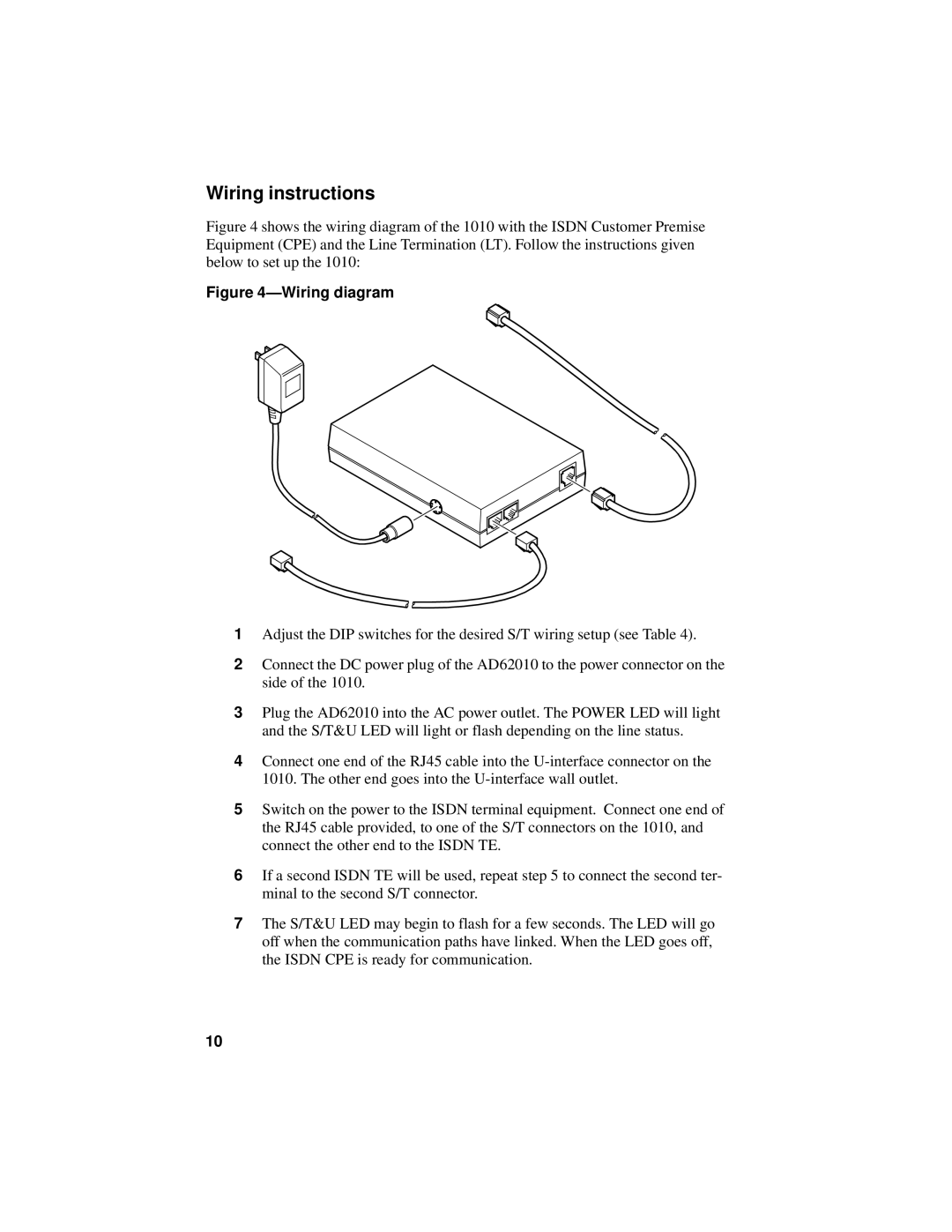
Figure 4 shows the wiring diagram of the 1010 with the ISDN Customer Premise Equipment (CPE) and the Line Termination (LT). Follow the instructions given below to set up the 1010:
Figure 4—Wiring diagram
1Adjust the DIP switches for the desired S/T wiring setup (see Table 4).
2Connect the DC power plug of the AD62010 to the power connector on the side of the 1010.
3Plug the AD62010 into the AC power outlet. The POWER LED will light and the S/T&U LED will light or flash depending on the line status.
4Connect one end of the RJ45 cable into the
5Switch on the power to the ISDN terminal equipment. Connect one end of the RJ45 cable provided, to one of the S/T connectors on the 1010, and connect the other end to the ISDN TE.
6If a second ISDN TE will be used, repeat step 5 to connect the second ter- minal to the second S/T connector.
7The S/T&U LED may begin to flash for a few seconds. The LED will go off when the communication paths have linked. When the LED goes off, the ISDN CPE is ready for communication.
10