Table |
| ||
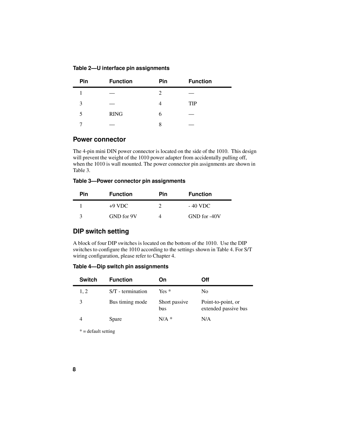
Pin | Function | Pin | Function |
|
|
|
|
1 | — | 2 | — |
3 | — | 4 | TIP |
5 | RING | 6 | — |
7 | — | 8 | — |
Power connector
The
Table 3—Power connector pin assignments
Pin | Function | Pin | Function |
|
|
|
|
1 | +9 VDC | 2 | - 40 VDC |
3 | GND for 9V | 4 | GND for |
DIP switch setting
A block of four DIP switches is located on the bottom of the 1010. Use the DIP switches to configure the 1010 according to the settings shown in Table 4. For S/T wiring configuration, please refer to Chapter 4.
Table 4—Dip switch pin assignments
Switch | Function | On | Off |
|
|
|
|
1, 2 | S/T - termination | Yes * | No |
3 | Bus timing mode | Short passive | |
|
| bus | extended passive bus |
4 | Spare | N/A * | N/A |
* = default setting
8