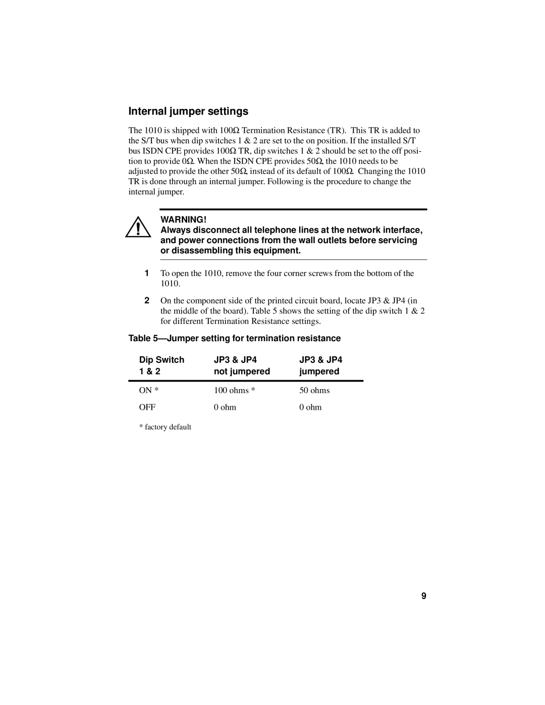
Internal jumper settings
The 1010 is shipped with 100Ω Termination Resistance (TR). This TR is added to the S/T bus when dip switches 1 & 2 are set to the on position. If the installed S/T bus ISDN CPE provides 100Ω TR, dip switches 1 & 2 should be set to the off posi- tion to provide 0Ω. When the ISDN CPE provides 50Ω, the 1010 needs to be adjusted to provide the other 50Ω, instead of its default of 100Ω. Changing the 1010 TR is done through an internal jumper. Following is the procedure to change the internal jumper.
WARNING!
Always disconnect all telephone lines at the network interface, and power connections from the wall outlets before servicing or disassembling this equipment.
1To open the 1010, remove the four corner screws from the bottom of the 1010.
2On the component side of the printed circuit board, locate JP3 & JP4 (in the middle of the board). Table 5 shows the setting of the dip switch 1 & 2 for different Termination Resistance settings.
Table
Dip Switch | JP3 & JP4 | JP3 & JP4 |
1 & 2 | not jumpered | jumpered |
|
|
|
ON * | 100 ohms * | 50 ohms |
OFF | 0 ohm | 0 ohm |
* factory default |
|
|
9
