Overview
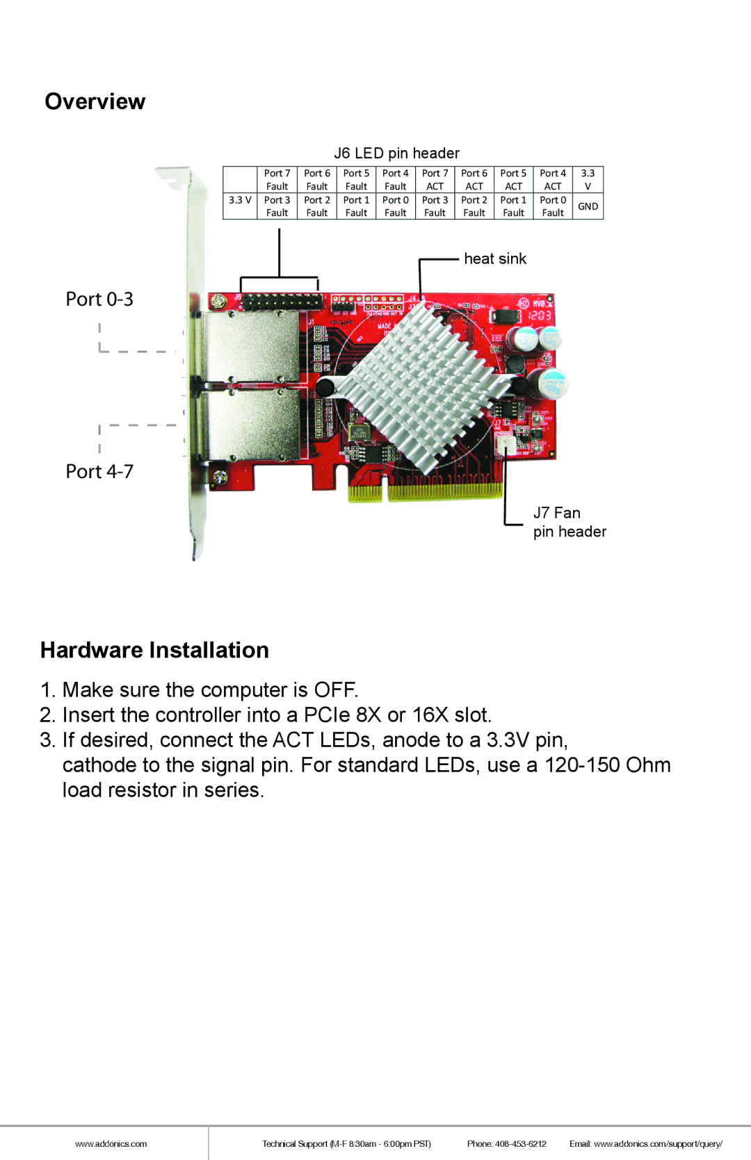
J6 LED pin header
Port 7 | Port 6 | Port 5 | Port 4 | Port 7 | Port 6 | Port 5 | Port 4 | 3.3 | |
Fault | Fault | Fault | Fault | ACT | ACT | ACT | ACT | V | |
3.3 V Port 3 | Port 2 | Port 1 | Port 0 | Port 3 | Port 2 | Port 1 | Port 0 | GND | |
Fault | Fault | Fault | Fault | Fault | Fault | Fault | Fault | ||
|
heat sink
Port
Port
J7 Fan pin header
Hardware Installation
1.Make sure the computer is OFF.
2.Insert the controller into a PCIe 8X or 16X slot.
3.If desired, connect the ACT LEDs, anode to a 3.3V pin,
cathode to the signal pin. For standard LEDs, use a
www.addonics.com
Technical Support | Phone: | Email: www.addonics.com/support/query/ |