NT1 ACE User Manual
Extended Passive Bus Configuration
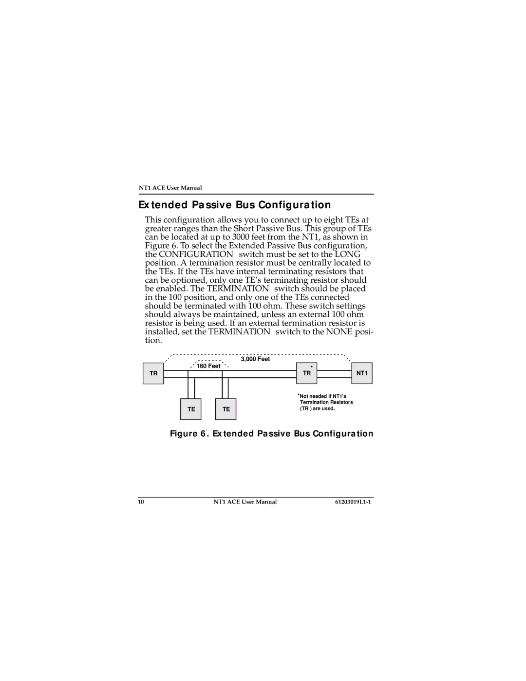
This configuration allows you to connect up to eight TEs at greater ranges than the Short Passive Bus. This group of TEs can be located at up to 3000 feet from the NT1, as shown in Figure 6. To select the Extended Passive Bus configuration, the CONFIGURATION switch must be set to the LONG position. A termination resistor must be centrally located to the TEs. If the TEs have internal terminating resistors that can be optioned, only one TE’s terminating resistor should be enabled. The TERMINATION switch should be placed in the 100 position, and only one of the TEs connected should be terminated with 100 ohm. These switch settings should always be maintained, unless an external 100 ohm resistor is being used. If an external termination resistor is installed, set the TERMINATION switch to the NONE posi- tion.
TR
3,000 Feet
160Feet
TETE
* | NT1 |
TR |
*Not needed if NT1's Termination Resistors (TR ) are used.
Figure 6. Extended Passive Bus Configuration
10 | NT1 ACE User Manual |
|