NT1 ACE User Manual
The switch labeled TERMINATION sets the Local Bus ter- mination. The options available are NONE, 50, and 100. See Powering TEs from the NT1 ACE on page 6 for more informa- tion concerning Local Bus configurations.
The switch labeled CONFIGURATION has two possible options. When set in the LONG position, the Local Bus is configured for Extended Passive Bus. When set in the SHORT position, the Local Bus is configured for Short Pas- sive Bus. Configuration and switch settings are discussed in Short Passive Bus Configuration on page 9 and in Extended Passive Bus Configuration on page 10.
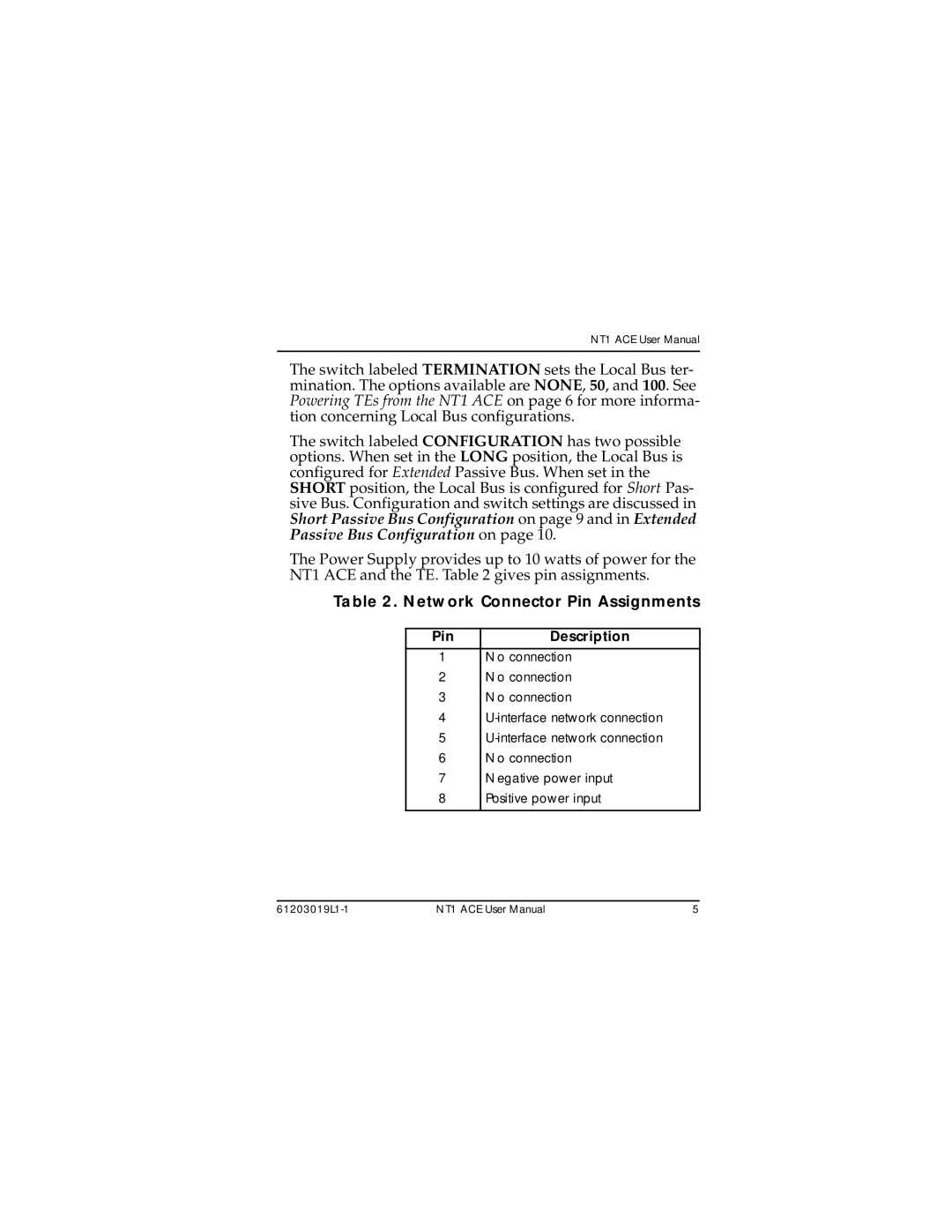
The Power Supply provides up to 10 watts of power for the NT1 ACE and the TE. Table 2 gives pin assignments.
Table 2. Network Connector Pin Assignments
Pin | Description |
1 | No connection |
2 | No connection |
3 | No connection |
4 | |
5 | |
6 | No connection |
7 | Negative power input |
8 | Positive power input |
|
|
| NT1 ACE User Manual | 5 |