3M Industrial Adhesives and Tapes
3M 2011 44-0009-2077-5 B070811-NA
Page
Industrial Adhesives and Tapes
This page is Blank
Safety
Introduction
General Information
This page is Blank
Table of Contents Shipment, Handling, and Storage
Installation
Safety devices
Unpacking
This page is Blank
Taping Head Information
Abbreviations and Acronyms List of ABBREVIATIONS, Acronyms
Manufacturing Specifications / Description / Intended Use
Introduction
3M-MaticTM700r Random Case Sealer, Type
Manual Maintenance
Importance of the Manual
Consulting the Manual
General Information
Data Identifying Manufacturer and Machine
Contents-700r Random Case Sealer
Safety
General Safety Information
Explanation of Signal Word and Possible Consequences
To reduce the risk associated with hazardous voltage
To reduce the risk associated with sharp blade hazards
To reduce the risk associated with muscle strain
To reduce the risk associated with pinch hazards
Personal Safety Measures
Operators Qualifications
Number of Operators
Residual Hazards
Skill 2 Mechanical Maintenance Technician
Skill 2a Electrical Maintenance Technician
Skill 1 Machine Operator
Assembly Roll Mount
Component Locations
10 Replacement Labels/3M Part Numbers 78-8070-1329-3
11 Replacement Labels/3M Part Numbers
12 Replacement Labels/3M Part Numbers
Specifications
Specifications Tape Roll Diameter
Box Weight and Size Capacities
Tape Application Leg Length Standard
Tape Application Leg Length Optional
Setup Recommendations
Machine Noise Level
SHIPMENT-HANDLING-STORAGE, Transport
Packaging for Overseas Shipment Optional Figure
Handling and Transportation of Uncrated Machine
Storage of the Packed or Unpacked Machine
Unpacking
Uncrating
Removal of Pallet
Installation
M8 x 1.25mm Socket Head Screws Adjustable Legs
Machine Positioning / Bed Height
Tool Kit Supplied with the Machine
Installation Removal of Plastic Ties
Assembly Completion / Machine Setup
Position Figure
Installation Machine Setup
See -7B
To reduce the risk associated with impact hazards
Installation and Setup Column Guards
700r Frame Setup
Installation and Setup Infeed Conveyor Assembly
Centering Guides
Outboard Tape Roll Mounting
Tape Leg Length
Box Size Capacity of Case Sealer
Electrical Connections and Controls
Initial Start-Up of Case Sealer
13 700r Case Sealer Components Left Front View
Adjust
Air Supply Filter Connector
Up to
Down
Centering Switch, Box Centering Guide
16- Air Regulator, Centering Guides Locking Nut
Installation and Setup
Mechanical Latch, Upper Drive Assembly
Main Air Pressure Gauge
Theory of Operation Box Centering Switch
Raising Switch
Tape Loading/Threading
To reduce the risk associated with pinch and impact hazards
Installation and Setup Tape Loading and Threading
Box Sealing
Installation Completion of Taping Heads
Inspection of Phases For Three-Main Phases Only
Outboard Tape Roll Holder
Preliminary Electric Inspection
Theory of Operation
Regulator Air Supply Filter Connector
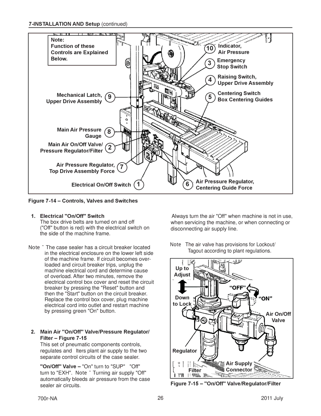
Controls
700r-NA July
700r-NA July
Safety Devices of the Machine
Blade Guards
Emergency Stop Button
Electric System / Circuit Breaker
SET UP and Adjustments
Maintenance and Repairs
Operation
Troubleshooting
Troubleshooting Guide Problem Cause Correction
Page
Maintenance and Repairs
Box Drive Belt Replacement Lower Drive Belts
Upper Drive Belts
Maintenance and Repairs Drive Pulley Rings
Box Drive Belt Tension
Box Drive Belt Tension Adjustment, Lower Belts Infeed End
Page
Special Setup Procedure Column Bumper Installation
Installation Instructions Column Bumper
Shown is after Safety Guard is Removed
Safety Guard Set Screws Washers
Box and Machine Bed Height Range Refer to Figure
Box Height Range Refer to -11 / .4 / and Specif cations
This page is Blank
700r-NA July
This page is Blank
Emergency Procedures
List of Safety Features
Additional Instructions Enclosures / Special Info
Emission of Hazardous Substances
Technical Diagrams
Electric Diagram
Page
This page is Blank
Machine Model Serial Number
Labels
This page is Blank
Options and Accessories
Part Number Option/Accessory
This page is Blank
700r Random Case Sealer Frame Assemblies 700r-NA July
15 21
700r Ref. No 3M Part No Description
Caster
Option
Optional
Caster Option
CB a
700r Ref. No 3M Part No Description
18a 18b
700r Ref. No 3M Part No Description
700r 700r Random Case Sealer
700r Ref. No 3M Part No Description
71 R/H 72 L/H
700r Ref. No 3M Part No Description
16 =
700r Ref. No 3M Part No Description
68 R/H 69 L/H
700r Ref. No 3M Part No Description
700r Random Case Sealer
700r Ref. No 3M Part No Description
700r 700r Random Case Sealer
700r Ref. No 3M Part No Description
700r Random Case Sealer
700r Ref. No 3M Part No Description
13 1415
700r Ref. No 3M Part No Description
This page is Blank
3M-Matic Accuglide Upper Lower High Speed Taping Heads Inch
3M 2012 44-0009-2070-0 E010712-NA
Page
3M-Matic, AccuGlide and Scotch
This page is Blank
3M-Matic , AccuGlide and Scotch
This page is Blank
Yellow
Page
Intended Use
AccuGlide 3 Upper Taping Head 2 inch, Type
This page is Blank
General Information How to use this Manual
Updating the Manual
Them Before Installing or Operating this Equipment
To reduce the risk associated with mechanical hazards
Important Safeguards
Replacement Labels/3M Part Numbers
Specifications Tape
Taping Head Dimensions
Box Size Capacities
Dimensional Drawing
Installation Guidelines
Tape Width Adjustment
Receiving And Handling
To reduce risk associated with muscle strain
Page
Tape Loading Upper Taping Head
Tape Loading Lower Taping Head
One-Way Tension Roller Wrap Knurled Applying
AccuGlide 3 2 NA January
Blade Guard
To reduce the risk associated with
Sharp blade hazards Blade Oiler Pad
Sharp blade hazards
Applying/Buffing Roller Replacement
Hex Socket Section View 5mm HexRoller/Shaft Key Wrench
Tape Latch Alignment Figure
Tape Drum Friction Brake Figure
Applying Mechanism Spring
One-Way Tension Roller
Leading Tape Leg Length Adjustment Figure
Leading Tape Leg Length One-Way Position a
Page
Page
Spare Parts/Service Information Recommended Spare Parts
Replacement Parts and Service
Qty Part Number Description
Page
AccuGlide 3 Tape Head AccuGlide 3 2 inch
Haute Bas AccuGlide January
AccuGlide 3
Upper Head AccuGlide 3 2 NA January
Upper Head Ref. No 3M Part No Description
Upper and Lower Heads
Upper and Lower Heads Ref. No 3M Part No Description
Upper Head
Upper Head Ref. No 3M Part No Description
Upper and Lower Heads AccuGlide 3 2 NA January July
Upper and Lower Heads Ref. No 3M Part No Description
Upper and Lower Heads
Upper and Lower Heads Ref. No 3M Part No Description
Upper and Lower Heads AccuGlide 3 2 NA January
Latch Upper and Lower Heads Ref. No 3M Part No Description
Lower Head AccuGlide 3 2 NA January
Lower Head Ref. No 3M Part No Description
Lower Head
Lower Head Ref. No 3M Part No Description
This page is Blank