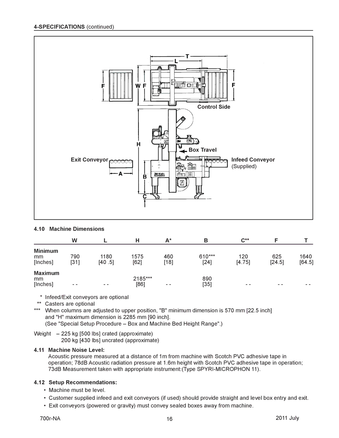
40800 specifications
3M 40800,800RF is an advanced adhesive tape that has gained popularity across various industries due to its innovative features and versatile applications. This product is characterized by its strong bonding capabilities, durability, and easy application, making it a go-to choice for professionals and DIY enthusiasts alike.One of the main features of 3M 40800,800RF is its exceptional adhesive strength. Designed to provide a reliable bond on a wide range of surfaces, including plastics, metal, glass, and paper, this tape ensures a strong and long-lasting hold. The adhesive technology utilized in the 3M 40800,800RF is formulated to provide superior performance even in challenging conditions, such as humidity or temperature fluctuations.
Another significant characteristic of this adhesive tape is its shear strength. 3M has engineered the tape to resist slippage and ensure that the bond remains intact over time. This quality is particularly beneficial in applications that require precision and stability, such as automotive and aerospace industries, where any failure in adhesion could lead to serious consequences.
The 3M 40800,800RF also offers remarkable flexibility, allowing it to conform to complex surfaces and irregular shapes. This feature enhances its usability in a variety of settings, enabling users to apply the tape with ease, regardless of the surface profile. Additionally, the tape's easy unwind feature simplifies the application process, reducing the risk of tearing or malfunction.
Another technology that sets 3M 40800,800RF apart is its resistance to chemicals and environmental factors. It is designed to withstand various chemicals, including oils and solvents, which makes it suitable for industrial applications. Furthermore, its ability to endure exposure to UV light without degrading ensures that the tape maintains its properties over extended periods of time, even when used in outdoor settings.
In summary, the 3M 40800,800RF adhesive tape stands out for its strength, flexibility, and versatility. With advanced adhesive technology, excellent shear strength, and high resistance to environmental factors, it is a reliable choice for a wide array of applications. Whether used in manufacturing, automotive, or general maintenance, this adhesive tape delivers exceptional performance, making it a preferred option for consumers looking for quality and reliability.

