106 Appendix D: Technical information Matrox Meteor-II /Digital
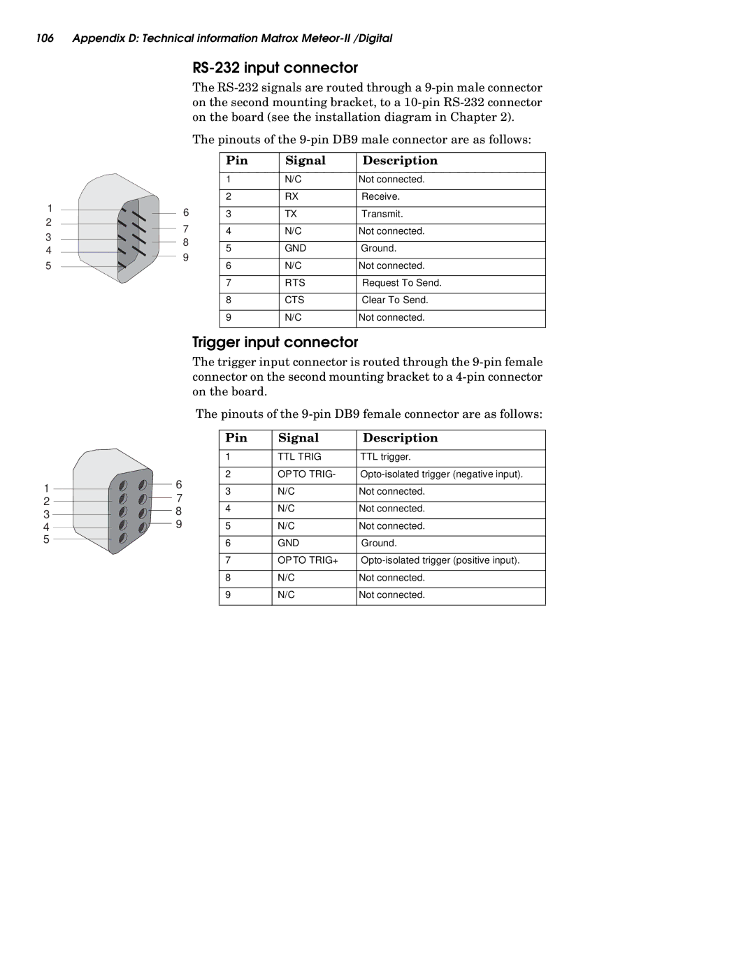
RS-232 input connector
The
|
| The pinouts of the | |||
|
| Pin | Signal | Description | |
|
| 1 | N/C | Not connected. | |
|
| 2 | RX | Receive. | |
1 | 6 | 3 | TX | Transmit. | |
2 | |||||
7 | 4 | N/C | Not connected. | ||
3 | |||||
8 | 5 | GND | Ground. | ||
4 | |||||
9 | |||||
5 | 6 | N/C | Not connected. | ||
| |||||
|
| 7 | RTS | Request To Send. | |
|
| 8 | CTS | Clear To Send. | |
|
| 9 | N/C | Not connected. | |
Trigger input connector
The trigger input connector is routed through the
|
| The pinouts of the | |||
|
| Pin | Signal | Description | |
|
| 1 | TTL TRIG | TTL trigger. | |
|
| 2 | OPTO TRIG- | ||
1 | 6 | 3 | N/C | Not connected. | |
7 | |||||
2 | 4 | N/C | Not connected. | ||
8 | |||||
3 | |||||
|
|
| |||
9 | 5 | N/C | Not connected. | ||
4 | |||||
5 |
| 6 | GND | Ground. | |
|
| ||||
|
| 7 | OPTO TRIG+ | ||
|
| 8 | N/C | Not connected. | |
|
| 9 | N/C | Not connected. | |